PA78EU Cirrus Logic Inc, PA78EU Datasheet - Page 6
PA78EU
Manufacturer Part Number
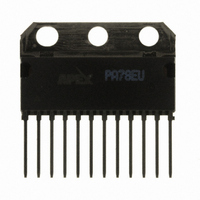
PA78EU
Description
IC PWR AMP 350V 200MA 12SIP
Manufacturer
Cirrus Logic Inc
Series
Apex Precision Power™r
Specifications of PA78EU
Amplifier Type
Power
Number Of Circuits
1
Slew Rate
350 V/µs
Gain Bandwidth Product
1MHz
Current - Input Bias
8.5pA
Voltage - Input Offset
8000µV
Current - Supply
700µA
Current - Output / Channel
150mA
Voltage - Supply, Single/dual (±)
20 V ~ 350 V, ±10 V ~ 175 V
Operating Temperature
-40°C ~ 125°C
Mounting Type
Through Hole
Package / Case
12-SIP
For Use With
598-1398 - KIT EVALUATION PA78/PA79598-1395 - EVALUATION KIT FOR PA78
Lead Free Status / RoHS Status
Lead free / RoHS Compliant
Output Type
-
-3db Bandwidth
-
Other names
598-1440
PA78EU
PA78EU
Available stocks
Company
Part Number
Manufacturer
Quantity
Price

Part Number:
PA78EU
Manufacturer:
APEX
Quantity:
20 000


Iv. DEFLECTION PLATES DRIvER wITH OvERDRIvE
pared with Figure 5, is that it is assumed that the deflection
plates are driven via a 25-foot length of coax that exhibits a
capacitance of 19.5 pf per foot — or 487.5 pf. Because of
this capacitive loading it is a bit more difficult to achieve a
satisfactory rise time.
develop an output of 0 to +300V that reaches 299V — or within
1V of the targeted voltage value — within 1.5 microseconds.
Again a PA78 power operational amplifier is employed with its
ability to source and sink (push and pull) pull current from the
differential input stage through the compensation capacitors
and the gate-to-source capacitances of the drive stage of the
amplifier. As long as the voltage differential across the PA78 +
and - inputs is 10V or more, the specified slew rate of greater
than 350V per microsecond is maintained.
exhibit this slew rate with little or no overshoot as the amplifier
reaches its target voltage. However, as the output of the PA78
approaches its programmed voltage, the (-) input of the PA78
also approaches the non-inverting input (+), thereby reducing
the differential voltage and therefore the slew rate.
of this application, any reduction in the slew rate as the output
voltage approaches its target value is unacceptable. However,
if a high-speed, small-signal, amplifier is utilized to overdrive the
input, the interval of high slew rate can be extended, thereby
maintaining a high differential voltage. In this scenario a high
slew rate is extended until the amplifier is within 1 volt of the
target value (300V).
the potential at the false summing node (Node B), as depicted
in Figure 6. The selection of this amplifier need not be limited
to the AD817, but a high gain-bandwidth product is critical as
well as a slew rate of 300V/μs or more.
creates a replica of the real summing node (Node A), at the
'False Summing Node' (Node B). The latter can be monitored
without injecting currents into the real summing node at Node
A, as this would cause significant static and dynamic errors.
This offset voltage is amplified by the AD817 and added as
an offset voltage to the (+) input terminal of the PA78. Thus
the amplified value of the potential at Node B supplies the
overdrive necessary to extend the region of high slew rate to
within 1V of the target value
REFERENCES
1. Apex Microtechnology Corp, Application Note 20 – Bridge Mode Operation of Power Operational Amplifiers, www.apexmi-
2. Apex Microtechnology Corp, Application Note 21, Section 3.1 – Single Supply Operation of Power Operational Amplifiers,
3. Apex Microtechnology Corp, Application Note 1, Section 7.2 – General Operating Considerations, www.apexmicrotech.com
BIBLIOGRAPHY
"Drive Piezoelectric Actuators With Fast, High-Power Op Amps", by Sam Robinson, Electronic Design Magazine, November
APEX MICROTECHNOLOGY CORPORATION • 5980 NORTH SHANNON ROAD • TuCSON, ARIZONA 85741 • uSA • APPLICATIONS HOTLINE: 1 (800) 546-2739
6
What is different about the circuit shown in Figure 6, com-
Again a DAC delivers a voltage, this time from zero to -3V to
In general, the design topology depicted in Figure 5, will
To meet the 300V swing, as well as the settling requirement
To achieve this, an AD817 is employed to invert and amplify
A pair of resistors of the same ratio as R
crotech.com
www.apexmicrotech.com
7th, 2005
This document has been carefully checked and is believed to be reliable, however, no responsibility is assumed for possible inaccuracies.
5
PA78RDU REV 3 JANUARY 2007 © 2007 Apex Microtechnology Corp.
and R
6
of the PA78
feedback resistors. To perform effectively, the AD817 requires
that the summing node impedances be as low as possible.
The false summing node resistors in parallel, R
series with the 10-ohm resistor R
in turn is connected to the R
summing node impedance. The resistance value of the false
summing node R
sure that the AD817 summing node impedance is low.
feedback resistors. The value of the feedback resistor R
33 kilohms, is a compromise between power dissipation and
parasitic capacitance.
resistance possible because the power consumption goes
as the inverse of the resistance and thereby is reduced with
a larger resistance. However, the distributed capacitance of
a resistor rises as its resistance rises. This tends to slow the
slew rate. By connecting several resistors in series to form R
and thus connecting the distributed capacitances in series,
the resulting value is less than the distributed capacitance of
either resistor alone.
power dissipation without adversely affecting the feedback
capacitance.
the capacitive load. There is a small amount of power dissi-
pated as the capacitor charges, but the final voltage plateau
is unaffected.
overdrive circuit could cause overshoot and excessive settling
times. However, by connecting the capacitor in parallel with R
the overshoot is dampened, without creating stability problems
or reducing the slew rate which would be the case if a true
feedback capacitor of a much higher value were connected
in parallel with R
node pairs and the gain of the AD817. Simulation has confirmed
that by employing 1% resistors, together with the worst case
tolerance of the active components, the closed-loop gain error
is held to no more than 4%.
What follows is a discussion of the passive components:
R
R
To reduce power dissipation you could chose the largest
This series combination of several resistors is able to reduce
R
C
The overall gain of the circuit is governed by both summing
3
5
9
1
— Without the false summing feedback capacitor C
and R
and R
— The isolation resistor R
4
6
— These are the false summing node input and
— These are the real summing node input and
3
4
-R
.
4
(100-ohm, 10-kilohm) combination makes
2
feedback resistor to form the
9
1
, and the equivalent resistor,
eliminates instability due to
3
and R
4
, are in
1
, the
6
6
4
,
,
,
Related parts for PA78EU
Image
Part Number
Description
Manufacturer
Datasheet
Request
R

Part Number:
Description:
Development Kit
Manufacturer:
Cirrus Logic Inc
Datasheet:
Part Number:
Description:
Development Kit
Manufacturer:
Cirrus Logic Inc
Datasheet:


Part Number:
Description:
High-efficiency PFC + Fluorescent Lamp Driver Reference Design
Manufacturer:
Cirrus Logic Inc
Datasheet:
Part Number:
Description:
Development Kit
Manufacturer:
Cirrus Logic Inc
Datasheet:
Part Number:
Description:
Development Kit
Manufacturer:
Cirrus Logic Inc
Datasheet:

Part Number:
Description:
Development Kit
Manufacturer:
Cirrus Logic Inc
Datasheet:
Part Number:
Description:
Development Kit
Manufacturer:
Cirrus Logic Inc
Datasheet:
Part Number:
Description:
Development Kit
Manufacturer:
Cirrus Logic Inc
Datasheet:
Part Number:
Description:
Development Kit
Manufacturer:
Cirrus Logic Inc
Datasheet:

Part Number:
Description:
EVALUATION BOARD FOR CS8427
Manufacturer:
Cirrus Logic Inc
Datasheet:

Part Number:
Description:
BOARD EVAL FOR CS8416 RCVR
Manufacturer:
Cirrus Logic Inc
Datasheet:

Part Number:
Description:
EVALUATION BOARD FOR CS8420
Manufacturer:
Cirrus Logic Inc
Datasheet:

Part Number:
Description:
KIT DEVELOPMENT EP9315 ARM9
Manufacturer:
Cirrus Logic Inc
Datasheet:

Part Number:
Description:
KIT DEVELOPMENT EP9302 ARM9
Manufacturer:
Cirrus Logic Inc
Datasheet: