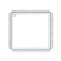
XR16L784IV-F Exar Corporation, XR16L784IV-F Datasheet - Page 23

XR16L784IV-F
Manufacturer Part Number
XR16L784IV-F
Description
IC UART 8B 3.3V QUAD 64LQFP
Manufacturer
Exar Corporation
Type
IrDA or RS- 485r
Datasheet
1.XR16L784CV-F.pdf
(51 pages)
Specifications of XR16L784IV-F
Number Of Channels
4, QUART
Package / Case
64-LQFP
Features
*
Fifo's
64 Byte
Protocol
RS485
Voltage - Supply
2.97 V ~ 5.5 V
With Auto Flow Control
Yes
With Irda Encoder/decoder
Yes
With False Start Bit Detection
Yes
With Modem Control
Yes
Mounting Type
Surface Mount
Data Rate
6.25 Mbps
Supply Voltage (max)
5.5 V
Supply Voltage (min)
2.97 V
Supply Current
5 mA
Maximum Operating Temperature
+ 85 C
Minimum Operating Temperature
- 40 C
Mounting Style
SMD/SMT
Operating Supply Voltage
3.3 V or 5 V
No. Of Channels
4
Uart Features
Tx/Rx FIFO Counters
Supply Voltage Range
2.97V To 5.5V
Operating Temperature Range
-40°C To +85°C
Digital Ic Case Style
LQFP
Rohs Compliant
Yes
Lead Free Status / RoHS Status
Lead free / RoHS Compliant
Lead Free Status / RoHS Status
Lead free / RoHS Compliant, Lead free / RoHS Compliant
Other names
1016-1282
Available stocks
Company
Part Number
Manufacturer
Quantity
Price
Company:
Part Number:
XR16L784IV-F
Manufacturer:
Exar Corporation
Quantity:
10 000
Part Number:
XR16L784IV-F
Manufacturer:
EXAR/艾科嘉
Quantity:
20 000
REV. 1.2.3
TIMER [7:0] (default 0x00): Reserved.
TIMERMSB [7:0] and TIMERLSB [7:0]
TIMERMSB and TIMERLSB form a 16-bit value. The least-significant bit of the timer is being bit [0] of the
TIMERLSB with most-significant-bit being bit [7] in TIMERMSB. Reading the TIMERCNTL register will clear its
interrupt. Default value is zero upon powerup and reset.
Each bit selects 8X or 16X sampling rate for that UART channel, bit-0 is channel 0. Logic 0 (default) selects
normal 16X sampling with logic one selects 8X sampling rate. Transmit and receive data rates will double by
selecting 8X.
The 8-bit Reset register [RESET] provides the software with the ability to reset individual UART(s) when there
is a need. Each bit is self-resetting after it is written a logic 1 to perform a reset to that channel. All registers in
that channel will be reset to the default condition, see
UART channel 0 with bit-3=1 resets channel 3.
3.1.3
3.1.4
3.1.5
Bit-15
8XMODE [7:0] (default 0x00)
REGA [7:0] reserved
RESET [7:0] (default 0x00)
Bit-14
Bit-13
TIMERMSB Register
Bit-12
Bit-7 Bit-6 Bit-5 Bit-4 Bit-3 Bit-2
Rsvd
Bit-11
16-Bit Timer/Counter Programmable Registers
Bit-7 Bit-6 Bit-5 Bit-4 Bit-3 Bit-2 Bit-1 Bit-0
Rsvd
Bit-7 Bit-6 Bit-5 Bit-4 Bit-3 Bit-2 Bit-1 Bit-0
Individual UART Channel 8X Clock Mode Enable
Rsvd
(default 0x00)
Rsvd
Bit-10
Individual UART Channel Reset Enable
Rsvd
Rsvd
Rsvd
TIMERCNTL Register
Bit-9
Rsvd Rsvd Ch-3 Ch-2 Ch-1 Ch-0
Rsvd Rsvd Ch-3 Ch-2 Ch-1 Ch-0
8XMODE Register
RESET Register
Bit-8
Rsvd
23
Select
Clock
HIGH PERFORMANCE 2.97V TO 5.5V QUAD UART
Table 19
Bit-7
Re-trigger
Single/
Bit-6
for details. As an example, bit-0 =1 resets
Bit-1 Bit-0
Start/
Stop
Bit-5
TIMERLSB Register
Enable
Bit-4
INT
Bit-3
Bit-2
XR16L784
Bit-1
Bit-0


