STEVAL-PCC012V1 STMicroelectronics, STEVAL-PCC012V1 Datasheet - Page 15
STEVAL-PCC012V1
Manufacturer Part Number
STEVAL-PCC012V1
Description
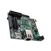
BOARD DEM CONN GATEWAY STM32F107
Manufacturer
STMicroelectronics
Series
STM32r
Type
Other Power Managementr
Datasheets
1.STM32F105V8T6.pdf
(101 pages)
2.STEVAL-PCC012V1.pdf
(10 pages)
3.EVALST7590-1.pdf
(43 pages)
Specifications of STEVAL-PCC012V1
Main Purpose
Interface, Connectivity
Embedded
Yes, MCU, 32-Bit
Utilized Ic / Part
STM32F107
Primary Attributes
Ethernet and 4 Digital/Analog Connectors
Secondary Attributes
On-Board LEDs and Joystick
Interface Type
Ethernet, USB, I2C, SPI, UART
Operating Supply Voltage
3.3 V
Product
Power Management Development Tools
Lead Free Status / RoHS Status
Lead free / RoHS Compliant
For Use With/related Products
STM32F107xx
Other names
497-10757
Available stocks
Company
Part Number
Manufacturer
Quantity
Price
Company:

Part Number:
STEVAL-PCC012V1
Manufacturer:
STMicroelectronics
Quantity:
1


STM32F105xx, STM32F107xx
2.3.9
2.3.10
2.3.11
2.3.12
Power supply schemes
●
●
●
Power supply supervisor
The device has an integrated power-on reset (POR)/power-down reset (PDR) circuitry. It is
always active, and ensures proper operation starting from/down to 2 V. The device remains
in reset mode when V
external reset circuit.
The device features an embedded programmable voltage detector (PVD) that monitors the
V
generated when V
than the V
message and/or put the MCU into a safe state. The PVD is enabled by software.
Voltage regulator
The regulator has three operation modes: main (MR), low power (LPR) and power down.
●
●
●
This regulator is always enabled after reset. It is disabled in Standby mode.
Low-power modes
The STM32F105xx and STM32F107xx connectivity line supports three low-power modes to
achieve the best compromise between low power consumption, short startup time and
available wakeup sources:
●
●
DD
/V
V
Provided externally through V
V
and PLL (minimum voltage to be applied to V
and V
V
registers (through power switch) when V
MR is used in the nominal regulation mode (Run)
LPR is used in the Stop modes.
Power down is used in Standby mode: the regulator output is in high impedance: the
kernel circuitry is powered down, inducing zero consumption (but the contents of the
registers and SRAM are lost)
Sleep mode
In Sleep mode, only the CPU is stopped. All peripherals continue to operate and can
wake up the CPU when an interrupt/event occurs.
Stop mode
Stop mode achieves the lowest power consumption while retaining the content of
SRAM and registers. All clocks in the 1.8 V domain are stopped, the PLL, the HSI RC
and the HSE crystal oscillators are disabled. The voltage regulator can also be put
either in normal or in low-power mode.
The device can be woken up from Stop mode by any of the EXTI line. The EXTI line
source can be one of the 16 external lines, the PVD output, the RTC alarm or the USB
OTG FS wakeup.
DD
SSA
BAT
DDA
= 2.0 to 3.6 V: external power supply for I/Os and the internal regulator.
, V
= 1.8 to 3.6 V: power supply for RTC, external clock 32 kHz oscillator and backup
PVD
power supply and compares it to the V
SSA
DDA
threshold. The interrupt service routine can then generate a warning
must be connected to V
= 2.0 to 3.6 V: external analog power supplies for ADC, Reset blocks, RCs
DD
/V
DD
DDA
is below a specified threshold, V
drops below the V
Doc ID 15274 Rev 5
DD
pins.
DD
and V
DD
PVD
SS
is not present.
PVD
threshold and/or when V
DDA
, respectively.
threshold. An interrupt can be
is 2.4 V when the ADC is used). V
POR/PDR
, without the need for an
DD
/V
DDA
Description
is higher
15/101
DDA
Related parts for STEVAL-PCC012V1
Image
Part Number
Description
Manufacturer
Datasheet
Request
R

Part Number:
Description:
Interface Development Tools Opto ISO USB Bridge 8-Pin Motor CTRL BRD
Manufacturer:
STMicroelectronics
Datasheet:

Part Number:
Description:
BOARD EVAL FOR MEMS SENSORS
Manufacturer:
STMicroelectronics
Datasheet:
Part Number:
Description:
EVALBOARD/STEVAL-ISV014V1
Manufacturer:
STMicroelectronics
Part Number:
Description:
BOARD EVAL FOR ST802RT1
Manufacturer:
STMicroelectronics
Datasheet:

Part Number:
Description:
BOARD EVAL FOR VACUUM CLEANER
Manufacturer:
STMicroelectronics
Datasheet:

Part Number:
Description:
KIT DEV STARTER ST10F276Z5
Manufacturer:
STMicroelectronics
Datasheet:

Part Number:
Description:
BOARD LED CTLR/DVR STLED316S
Manufacturer:
STMicroelectronics
Datasheet:

Part Number:
Description:
BOARD EVAL BLDC SENSORLESS MOTOR
Manufacturer:
STMicroelectronics
Datasheet:

Part Number:
Description:
BOARD ELECT FISCAL CASH REGISTER
Manufacturer:
STMicroelectronics
Datasheet:

Part Number:
Description:
BOARD EVAL BIPO SOLUTION FOR PFC
Manufacturer:
STMicroelectronics
Datasheet:
Part Number:
Description:
STMicroelectronics [RIPPLE-CARRY BINARY COUNTER/DIVIDERS]
Manufacturer:
STMicroelectronics
Datasheet:
Part Number:
Description:
STMicroelectronics [LIQUID-CRYSTAL DISPLAY DRIVERS]
Manufacturer:
STMicroelectronics
Datasheet:
Part Number:
Description:
BOARD EVAL FOR MEMS SENSORS
Manufacturer:
STMicroelectronics
Datasheet: