STEVAL-PCC012V1 STMicroelectronics, STEVAL-PCC012V1 Datasheet - Page 34
STEVAL-PCC012V1
Manufacturer Part Number
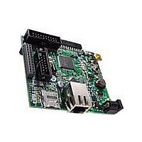
STEVAL-PCC012V1
Description
BOARD DEM CONN GATEWAY STM32F107
Manufacturer
STMicroelectronics
Series
STM32r
Type
Other Power Managementr
Datasheets
1.STM32F105V8T6.pdf
(101 pages)
2.STEVAL-PCC012V1.pdf
(10 pages)
3.EVALST7590-1.pdf
(43 pages)
Specifications of STEVAL-PCC012V1
Main Purpose
Interface, Connectivity
Embedded
Yes, MCU, 32-Bit
Utilized Ic / Part
STM32F107
Primary Attributes
Ethernet and 4 Digital/Analog Connectors
Secondary Attributes
On-Board LEDs and Joystick
Interface Type
Ethernet, USB, I2C, SPI, UART
Operating Supply Voltage
3.3 V
Product
Power Management Development Tools
Lead Free Status / RoHS Status
Lead free / RoHS Compliant
For Use With/related Products
STM32F107xx
Other names
497-10757
Available stocks
Company
Part Number
Manufacturer
Quantity
Price
Company:

Part Number:
STEVAL-PCC012V1
Manufacturer:
STMicroelectronics
Quantity:
1


Electrical characteristics
5.2
34/101
Absolute maximum ratings
Stresses above the absolute maximum ratings listed in
Table 7: Current
damage to the device. These are stress ratings only and functional operation of the device
at these conditions is not implied. Exposure to maximum rating conditions for extended
periods may affect device reliability.
Table 6.
1. All main power (V
2. I
Table 7.
1. All main power (V
2. I
3. Negative injection disturbs the analog performance of the device. See note in
4. When several inputs are submitted to a current injection, the maximum I
|V
V
I
V
INJ(PIN)
I
supply, in the permitted range.
maximum is respected. If V
externally to the I
induced by V
supply, in the permitted range.
cannot be respected, the injection current must be limited externally to the I
injection is induced by V
characteristics.
positive and negative injected currents (instantaneous values). These results are based on
characterization with I
Symbol
SSX
INJ(PIN)
INJ(PIN)
|V
ESD(HBM)
DD
Symbol
INJ(PIN)
V
I
I
–V
VDD
DDx
VSS
I
IN
V
IO
SS
must never be exceeded (see
(2)(3)
must never be exceeded. This is implicitly insured if V
|
SS
(2)
|
Voltage characteristics
Current characteristics
IN
External main supply voltage (including V
and V
Input voltage on five volt tolerant pin
Input voltage on any other pin
Variations between different V
Variations between all the different ground pins
Electrostatic discharge voltage (human body
model)
< V
characteristics, and
Total current into V
Total current out of V
Output current sunk by any I/O and control pin
Output current source by any I/Os and control pin
Injected current on NRST pin
Injected current on HSE OSC_IN and LSE OSC_IN pins
Injected current on any other pin
Total injected current (sum of all I/O and control pins)
INJ(PIN)
DD
DD
SS
, V
, V
DD
.
DDA
DDA
INJ(PIN)
)
IN
value. A positive injection is induced by V
(1)
> V
) and ground (V
) and ground (V
IN
maximum cannot be respected, the injection current must be limited
DD
maximum current injection on four I/O port pins of the device.
while a negative injection is induced by V
Doc ID 15274 Rev 5
Ratings
DD
Table 7: Current
SS
/V
Table 8: Thermal characteristics
SS
SS
DDA
ground lines (sink)
, V
, V
Ratings
SSA
SSA
(2)
power lines (source)
DD
) pins must always be connected to the external power
) pins must always be connected to the external power
power pins
(4)
(2)
characteristics). This is implicitly insured if V
DDA
IN
maximum is respected. If V
(1)
Table 6: Voltage
IN
> V
see
Absolute maximum ratings
(electrical sensitivity)
(1)
STM32F105xx, STM32F107xx
IN
V
V
INJ(PIN)
max while a negative injection is
SS
SS
IN
Section 5.3.11:
–0.3
INJ(PIN)
Min
(4)
< V
0.3
0.3
Section 5.3.16: 12-bit ADC
is the absolute sum of the
SS
may cause permanent
.
value. A positive
characteristics,
V
Max.
25
± 25
150
150
± 5
± 5
± 5
DD
25
Max
+5.5
IN
4.0
50
50
+0.3
maximum
IN
Unit
mA
Unit
mV
V
Related parts for STEVAL-PCC012V1
Image
Part Number
Description
Manufacturer
Datasheet
Request
R

Part Number:
Description:
Interface Development Tools Opto ISO USB Bridge 8-Pin Motor CTRL BRD
Manufacturer:
STMicroelectronics
Datasheet:

Part Number:
Description:
BOARD EVAL FOR MEMS SENSORS
Manufacturer:
STMicroelectronics
Datasheet:
Part Number:
Description:
EVALBOARD/STEVAL-ISV014V1
Manufacturer:
STMicroelectronics
Part Number:
Description:
BOARD EVAL FOR ST802RT1
Manufacturer:
STMicroelectronics
Datasheet:

Part Number:
Description:
BOARD EVAL FOR VACUUM CLEANER
Manufacturer:
STMicroelectronics
Datasheet:

Part Number:
Description:
KIT DEV STARTER ST10F276Z5
Manufacturer:
STMicroelectronics
Datasheet:

Part Number:
Description:
BOARD LED CTLR/DVR STLED316S
Manufacturer:
STMicroelectronics
Datasheet:

Part Number:
Description:
BOARD EVAL BLDC SENSORLESS MOTOR
Manufacturer:
STMicroelectronics
Datasheet:

Part Number:
Description:
BOARD ELECT FISCAL CASH REGISTER
Manufacturer:
STMicroelectronics
Datasheet:

Part Number:
Description:
BOARD EVAL BIPO SOLUTION FOR PFC
Manufacturer:
STMicroelectronics
Datasheet:
Part Number:
Description:
STMicroelectronics [RIPPLE-CARRY BINARY COUNTER/DIVIDERS]
Manufacturer:
STMicroelectronics
Datasheet:
Part Number:
Description:
STMicroelectronics [LIQUID-CRYSTAL DISPLAY DRIVERS]
Manufacturer:
STMicroelectronics
Datasheet:
Part Number:
Description:
BOARD EVAL FOR MEMS SENSORS
Manufacturer:
STMicroelectronics
Datasheet: