TWR-MCF51MM Freescale Semiconductor, TWR-MCF51MM Datasheet
TWR-MCF51MM
Specifications of TWR-MCF51MM


Related parts for TWR-MCF51MM


TWR-MCF51MM Summary of contents
Page 1
... Freescale Semiconductor Inc. TWR-MCF51MM User Manual Rev. 1.0 ...
Page 2
... Medical Connector .............................................................................................................................................................. 5 3.7 Elevator Connections ........................................................................................................................................................ 6 3.8 Mechanical Form Factor .................................................................................................................................................. 8 4 Jumper Table .............................................................................................................................................. 8 5 Input/Output Connectors and Pin Usage Table........................................................................... 10 6 OSBDM ........................................................................................................................................................ 10 6.1 Bootloader Mode For MC9S08JM60......................................................................................................................... 10 7 Bootloader Mode For MCF51MM256 .............................................................................................. 11 8 BDM inteface (Optional) ...................................................................................................................... 12 Contents TWR-MCF51MM User Manual Page ...
Page 3
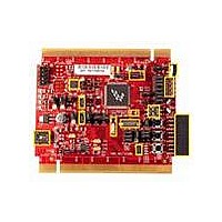
... Overview TWR-MCF51MM is a low-cost evaluation, demonstration and development board that features a 32-bit MCF51MM256 microcontroller. The TWR-MCF51MM can operate stand-alone or as the main control board in a Tower System with peripheral modules. The following list summarizes the features of the MCF51MM Tower MCU boards: ...
Page 4
... System Power The TWR-MCF51MM can be powered by the Open Source BDM (OSBDM) circuit via the Mini-B USB connector when stand-alone. When assembled with the Tower System and the TWR-SER is configured to run USB device mode (J16 pin 3 and 4 connected), the Mini-B USB connector is no longer used as a power source and only used for OSBDM debugging purposes ...
Page 5
... RS232 Interface An RS232 transceiver on the TWR-MCF51MM connects to a standard 2x5 pin header (refer to Figure 2). Selection jumpers J15 and J16 allow MCF51MM256 SCI2 signals to be routed to either the RS232 transceiver or the OSBDM circuit. Refer to Figure 5 for more details. Alternatively, when assembled as a Tower System, the MCF51MM256 SCI1 TX and RX are routed to the SER-TWR ...
Page 6
... The TWR-MCF51MM features two expansion card-edge connectors that interface to elevator boards in a Tower System: the Primary and Secondary Elevator connectors. The Primary Elevator connector, comprised of sides A and B, is utilized by the TWR-MCF51MM, while the Secondary Elevator connector only makes connections to ground (GND). Figure 4 provides the pinout for the Primary Elevator connector. An “ ...
Page 7
... A52 TDO / DSO A53 TMS / BKPT_b USB_DM A54 USB_DP X A55 USB_ID X A56 USB_VBUS X A57 TMR7 X A58 TWR-MCF51MM User Manual Usage Used Jmp TRIAMP1 negative input X TRIAMP2 output X TRIAMP1 output X OPAMP1 output X Ground X ADC differential minus X ADC differential plus X TRIAMP2 positive input ...
Page 8
... Power 3.8 Mechanical Form Factor The TWR-MCF51MM is designed for the Freescale Tower System and complies with the electrical and mechanical specification as described in Freescale Tower Electromechanical Specification. 4 Jumper Table There are several jumpers provided for isolation, configuration, and feature selection. Refer to the following table for details ...
Page 9
... Connects Infrared transistor output to ADP10 3-4 Connects Infrared transistor output to RX1 5-6 Connects either IRO or TX1 to Infrared diode base on J26 1-2 TX1 pin drives Infrared transmit 2-3 IRO pin drives Infrared transmit Open Connects to MED-EKG board TWR-MCF51MM User Manual pin of accelerometer Page ...
Page 10
... RS232 232_RXD ICL3232 232_TXD NOTE: LED1 to LED4 are labelled D12 on the TWR-MCF51MM silkscreen. 6 OSBDM An on-board, MC9S08JM60 based OSBDM circuit provides a debug interface to the MCF51MM256. The MC9S08JM60 is a USB-enabled microcontroller with an 8-bit HC9S08 core. The OSBDM circuit provides a USB-to-debug interface that allows run-control and debugging of the MCF51MM256 target device ...
Page 11
... MCF51MM256 for mass erase and programming via its USB interface. This on-chip bootloader does not consume user flash space. To enable USB bootloader mode for MCF51MM256, on the TWR-MCF51MM module, set SW3 DIP switch 2 and 3 to position 3, as indicated in Figure 7. NOTE: Under normal development you will need to set SW3 DIP switch 2 and 3 to position 2 ...
Page 12
... The BDM interface for MCF51MM256 is at J13 header and MC9S08JM60 is at J14 from the TWR-MCF51MM module. The user needs a P&E USB BDM MULTILINK in order to use this interface. This is a repeat function of the OSBDM and is not required. ...