TWR-MCF51MM Freescale Semiconductor, TWR-MCF51MM Datasheet - Page 9
TWR-MCF51MM
Manufacturer Part Number
TWR-MCF51MM
Description
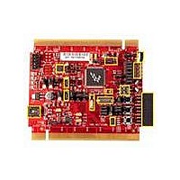
TOWER SYSTEM BOARD MCF51MM
Manufacturer
Freescale Semiconductor
Series
ColdFire®, Flexis™r
Type
MCUr
Specifications of TWR-MCF51MM
Contents
Board, 3 Modules, MED-EKG Kit, Cables, Documentation, DVD
Product
Microcontroller Modules
Data Bus Width
32 bit
Core Processor
MCF51MM
Clock Speed
32 KHz
Interface Type
RS232, RS485, CAN , USB
Flash
256 KB
Operating Supply Voltage
3.3 V
Silicon Manufacturer
Freescale
Core Architecture
Coldfire
Core Sub-architecture
Coldfire V1
Silicon Core Number
MCF51
Silicon Family Name
Flexis - MCF51MM
Rohs Compliant
Yes
For Use With/related Products
Freescale Tower System, MCF51MM
Lead Free Status / RoHS Status
Lead free / RoHS Compliant


J10
J11
J12
J13
J14
J15
J16
J18
J19
J20
J21
J24
J25
J26
J27
J5
J6
J7
J8
J9
DACO routing selection
DACO routing selection
TRIAMP routing selection
TRIAMP routing selection
Infrared receive routing
USB3.3V connection
MCU IDD measure
OSBDM Bootloader mode or
debugger mode selection
BDM connector for
MCF51MM256
BDM connector for JM60
SCI2 TXD Routing Selection
SCI2 RXD Routing Selection
LED & Accelerometer
connections
Accelerometer mode control
Accelerometer control
RS232 connector
Infrared filter connection
Infrared transmit routing
Infrared transmit routing
Medical board connector
TWR-MCF51MM User Manual
11-12 Connects ADP7 to ACCY
13-14 Connects ADP6 to ACCX
Open OSBDM IC in debugger mode .
Open BDM connector for MCF51MM256
Open BDM connector for MC9S08JM60
Open 2x5 RS232 connector
Open Connects to MED-EKG board
9-10
1-2
2-3
1-2
1-2
2-3
1-2
2-3
1-2
1-2
2-3
1-2
1-2
1-2
2-3
1-2
2-3
1-2
3-4
5-6
7-8
1-2
3-4
5-6
1-2
1-2
1-2
3-4
5-6
1-2
2-3
Connect DACO to VINP1 if pin 2-3 of J3 is connected
Connect DACO to a RC low pass filter
Connect DACO to medical connector J27 pin 8
Connect TRIOUT1 to TRIOUT_SEL2
Connect TRIOUT2 to TRIOUT_SEL2
Connect TRIOUT1 to TRIOUT_SEL1
Connect TRIOUT2 to TRIOUT_SEL1
Connect Infrared transistor output to CMPP1
USB3.3V connects to external 3.3V power supply
USB3.3V connects to on-chip USB 3.3V regulator output
For measuring MCF51MM256 current
OSBDM IC in bootloader mode(For OSBDM firmware
reprogramming)
Connect TX2 to the RS232 transceiver
Connect TX2 to the OSBDM debugger interface circuit
Connect RX2 to the RS232 transceiver
Connect RX2 to the OSBDM debugger interface circuit
Connects LED4 to pin PTE7/USB_VBUSVLD/TPM2CH3
Connects LED3 to pin PTF0/USB_ID/TPM2CH2
Connects LED2 to pin PTF1/RX2/USB_DP_DOWN/TPM2CH1
Connects LED1 to pin PTF2/TX2/USB_DM_DOWN/TPM2CH0
Connects ADP8 to ACCZ
Connects PTA3 to SELF TEST pin of accelerometer
Connects PTA6 to
Connects PTA5 to G-SELECT pin of accelerometer
Connects PTB0 to 0G-DETECT pin of accelerometer
Choose whether to filter Infrared output
Connects Infrared transistor output to ADP10
Connects Infrared transistor output to RX1
Connects either IRO or TX1 to Infrared diode base on J26
TX1 pin drives Infrared transmit
IRO pin drives Infrared transmit
SLEEP
pin of accelerometer
Page 9 of 12
Related parts for TWR-MCF51MM
Image
Part Number
Description
Manufacturer
Datasheet
Request
R

Part Number:
Description:
Power Management IC Development Tools Low-volt 3-phase MC
Manufacturer:
Freescale Semiconductor
Datasheet:
Part Number:
Description:
K53N512CMD100 TWR Module
Manufacturer:
Freescale Semiconductor
Datasheet:
Part Number:
Description:
TWR-K53N512 Dev Kit
Manufacturer:
Freescale Semiconductor
Datasheet:

Part Number:
Description:
CONV DC/DC TRI OUT 5,15,-15V
Manufacturer:
Murata Power Solutions Inc
Datasheet:

Part Number:
Description:
CONV DC/DC TRI OUT 5,12,-12V
Manufacturer:
Murata Power Solutions Inc
Datasheet:

Part Number:
Description:
CONV DC/DC TRI OUT 5,15,-15V
Manufacturer:
Murata Power Solutions Inc
Datasheet:

Part Number:
Description:
LCD MODULE FOR TWR SYSTEM
Manufacturer:
Freescale Semiconductor
Datasheet:

Part Number:
Description:
DC/DC TH 11W 5-5/12V Triple A
Manufacturer:
Murata Power Solutions Inc
Datasheet:


Part Number:
Description:
TOWER SYSTEM PROTO
Manufacturer:
Freescale Semiconductor
Datasheet:

Part Number:
Description:
TOWER ELEVATOR BOARDS HARDWARE
Manufacturer:
Freescale Semiconductor
Datasheet:

Part Number:
Description:
TOWER SERIAL I/O HARDWARE
Manufacturer:
Freescale Semiconductor
Datasheet:

Part Number:
Description:
TOWER SYSTEM BOARD MPC5125
Manufacturer:
Freescale Semiconductor
Datasheet: