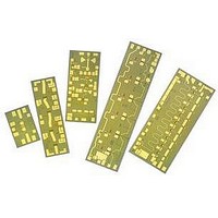
AMMC-6530-W50 Avago Technologies US Inc., AMMC-6530-W50 Datasheet

AMMC-6530-W50
Specifications of AMMC-6530-W50
Available stocks
Related parts for AMMC-6530-W50
AMMC-6530-W50 Summary of contents
Page 1
... Intended applications include microwave radios, 802.16, VSAT, and satellite receivers. Since this one mixer can cover several bands, the AMMC-6530 can reduce part inventory. The integrated mixer elimi- nates complex tuning and assembly processes typically required by hybrid (discrete-FET or diode) mixers ...
Page 2
... Input Port Power at 1dB gain compression point, Plo=+10 dBm NF Noise Figure Notes: 2. Small/Large signal data measured in a fully de-embedded test fixture form T 3. Specifications are derived from measurements in a 50Ω test environment. AMMC-6530 RF Specifications in Drain Pumped Test Configuration (T = 25° -1.0V +10 dBm ...
Page 3
... AMMC-6530 Typical Performance under Gate Pumped Down Conversion Operation (T = 25° -1V 50Ω drain gate Vg -1V LO Highly linear down conversion or up conversion mixer application (Gate pumped mixer operation -10 -15 -20 -25 -30 -35 -40 USB(dB) LSB(dB) -45 - FREQUENCY (GHz) Figure 1. Conversion Gain with IF terminated for High Side Conversion LO=+10 dBm, IF=1 GHz ...
Page 4
... AMMC-6530 Typical Performance under Gate Pumped Down Conversion Operation (T = 25° -1V, Z =50Ω -10 -15 Conv. Gain (dB) Return Loss (dB) - FREQUENCY (GHz) Figure 7. Conversion Gain and Match vs. IF Frequency. RF=20 GHz, LO=10 dBm -10 -15 - FREQUENCY (GHz) Figure 9. RF & LO Return Loss. LO=10 dBm. ...
Page 5
... AMMC-6530 Typical Performance under Gate Pumped Up Conversion Operation (T = 25° -1V, Z =50Ω LSB IF2 IF1 USB drain 0 USB (dB) -5 LSB (dB) -10 -15 -20 -25 -30 -35 -40 -45 - FREQUENCY (GHz) Figure 11. Up-conversion Gain with IF terminated for Low Side Conversion. LO=+5 dBm, IF=+5 dBm, IF=1 GHz. ...
Page 6
... AMMC-6530 Typical Performance under Drain Pumped Down Conversion Operation (T = 25° -1V 50Ω drain gate Vg RF -1V Low conversion loss mixer configuration (Drain pumped mixer operation -10 -15 -20 -25 -30 -35 -40 USB (dB) -45 LSB (dB) - FREQUENCY (GHz) Figure 15. Conversion Gain with IF terminated for Low Side Conversion. ...
Page 7
... There is no current consump- tion for the gate biasing because the FET mixer was designed for passive operation. For down conversion, the AMMC-6530 may be configured in a low loss or high linearity application low loss configuration, the LO is applied through the drain. In this configuration, the AMMC-6530 is a “ ...
Page 8
... This MMIC is also static sensitive and ESD precautions should be taken. Notes: 1. Ablebond 84-1 LM1 silver epoxy is recommended. 2. Eutectic attach is not recommended and may jeopardize reliability of the device. Part Number Ordering Information Part Number AMMC-6530-W10 AMMC-6530-W50 IF2 RF/LO www.avagotech.com Devices per Container 10 50 ...


