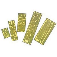
AMMC-6530-W50 Avago Technologies US Inc., AMMC-6530-W50 Datasheet - Page 7

AMMC-6530-W50
Manufacturer Part Number
AMMC-6530-W50
Description
IC MMIC IMAGE REJECT MXR 6-30GHZ
Manufacturer
Avago Technologies US Inc.
Series
AMMC-6530r
Datasheet
1.AMMC-6530-W50.pdf
(8 pages)
Specifications of AMMC-6530-W50
Function
Mixer
Noise Figure Typ
12dB
Supply Voltage Range
-1V
Frequency Max
30GHz
Frequency Min
5GHz
Supply Voltage Max
-3V
Gain
1dB
Lead Free Status / RoHS Status
Lead free / RoHS Compliant
Lead Free Status / RoHS Status
Lead free / RoHS Compliant, Lead free / RoHS Compliant
Available stocks
Company
Part Number
Manufacturer
Quantity
Price
Part Number:
AMMC-6530-W50
Manufacturer:
AVAGO/安华高
Quantity:
20 000
Biasing and Operation
The recommended DC bias condition for optimum
performance, and reliability is Vg = -1 volts. This can
be applied to either of the two Vg connections as they
are internally connected. There is no current consump-
tion for the gate biasing because the FET mixer was
designed for passive operation. For down conversion,
the AMMC-6530 may be configured in a low loss or high
linearity application. In a low loss configuration, the
LO is applied through the drain. In this configuration,
the AMMC-6530 is a “drain pumped mixer” . For higher
linearity applications, the LO is applied through the gate.
In this configuration, the AMMC-6530 is a “gate pumped
mixer” (or Resistive mixer). The mixer is also suitable for
up-conversion applications under the gate pumped
mixer operation shown on page 5.
Please note that the image rejection and isolation per-
formance is dependent on the selection of the low
frequency quadrature hybrid. The performance speci-
fication of the low frequency quadrature hybrid as well
as the phase balance and VSWR of the interface to the
AMMC-6530 will affect the overall mixer performance.
Assembly Techniques
The backside of the MMIC chip is RF ground. For mi-
crostrip applications the chip should be attached directly
to the ground plane (e.g. circuit carrier or heatsink) using
electrically conductive epoxy
For best performance, the topside of the MMIC should be
brought up to the same height as the circuit surround-
ing it. This can be accomplished by mounting a gold
plate metal shim (same length and width as the MMIC)
under the chip which is of correct thickness to make the
chip and adjacent circuit the same height. The amount of
epoxy used for the chip and/or shim attachment should
be just enough to provide a thin fillet around the bottom
perimeter of the chip or shim. The ground plane should
be free of any residue that may jeopardize electrical or
mechanical attachment.
The location of the RF bond pads is shown in Figure
7
[1, 2]
.
Figure 21. Simplified MMIC Schematic.
Figure 22. AMMC-6530 Bond Pad locations.


