XE1205SKC433XE1 Semtech, XE1205SKC433XE1 Datasheet - Page 13
XE1205SKC433XE1
Manufacturer Part Number
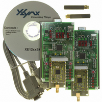
XE1205SKC433XE1
Description
KIT STARTER FOR XE1205 433MHZ
Manufacturer
Semtech
Series
TrueRF™r
Type
Transceiver, ISMr
Specifications of XE1205SKC433XE1
Frequency
433MHz
For Use With/related Products
XE1205 (433MHz)
Lead Free Status / RoHS Status
Contains lead / RoHS non-compliant


5.2.3.5
The block is switched ON by writing bit RXParam_FEI to ‘1’.This function provides information about the frequency error
of the local oscillator compared with the input carrier frequency and can be used to implement an external AFC. The
condition on the modulation index for proper behavior of the FEI function is:
Where Δf is the frequency deviation and BR is the bit rate.
The time diagram of an FEI measurement is given in the next figure. When the FEI block has been woken up and is
ready, and as long as the block is kept on, the frequency error is measured and the current result of the measurement is
loaded in the register RXParam_FEI_out(15:0) each time registers 12 is read. TS_FEI is the time required for the first
evaluation to be completed after the block has been started up and its value is given in section 4.2.2. Since the contents
of the configuration register is validated at the rising edge of the enable signal NSS_CONFIG, the FEI block is actually
started up at this time.
To guarantee proper behavior of the FEI, the operation must be done when a preamble as defined in section 5.2.3.1 is
received, and the sum of the frequency offset and the signal bandwidth (single sided) must be lower than the base band
filter bandwidth (single sided). That is:
F
Where f
(single side) equal to the sum of the bit rate divided by 2 and the frequency deviation (BR/2 + DF), and FilterBW is the
channel filter bandwidth defined by RXParam_BW(1:0) parameters.
The frequency error can be calculated by the following formula:
The frequency error = 500*int(FEI_out(15:0)) in Hz
Where int(x) is the integer value of the signed binary representation of x.
© Semtech 2008
β
offset
=
2
+ SignalBW < FilterBW.
BR
Δ ⋅
RXParam_FEI
NSS_CONFIG
fei_out_int
saout_fei
RXParam_FEI_out
offset
f
Frequency Error Indicator in continuous mode – FEI
≥
is the difference between the carrier frequency and the LO frequency, SignalBW is the signal bandwidth
, 2
TS_FEI
XXX
Figure 7: Timing diagram of an FEI measurement
0
val1
13
val2
Read RSSI
TS_FEI
val3
val2
val4
Read RSSI
val5
XE1205
val5
val6
www.semtech.com
0
Related parts for XE1205SKC433XE1
Image
Part Number
Description
Manufacturer
Datasheet
Request
R

Part Number:
Description:
Low-power, High Link Budget Integrated Uhf Transceiver
Manufacturer:
Semtech Corporation
Datasheet:

Part Number:
Description:
EVALUATION BOARD
Manufacturer:
Semtech
Datasheet:
Part Number:
Description:
EVALUATION BOARD
Manufacturer:
Semtech
Datasheet:
Part Number:
Description:
VOLTAGE SUPPRESSOR, TRANSIENT SEMTECH
Manufacturer:
Semtech
Datasheet:
Part Number:
Description:
HIGH VOLTAGE CAPACITORS MONOLITHIC CERAMIC TYPE
Manufacturer:
Semtech Corporation
Datasheet:
Part Number:
Description:
EZ1084CM5.0 AMP POSITIVE VOLTAGE REGULATOR
Manufacturer:
Semtech Corporation
Datasheet:
Part Number:
Description:
3.0 AMP LOW DROPOUT POSITIVE VOLTAGE REGULATORS
Manufacturer:
Semtech Corporation
Datasheet:
Part Number:
Description:
Manufacturer:
Semtech Corporation
Datasheet:
Part Number:
Description:
RailClamp Low Capacitance TVS Diode Array
Manufacturer:
Semtech Corporation
Datasheet:
Part Number:
Description:
Manufacturer:
Semtech Corporation
Datasheet:
Part Number:
Description:
Manufacturer:
Semtech Corporation
Datasheet:
Part Number:
Description:
Manufacturer:
Semtech Corporation
Datasheet: