EVAL-PIXIE Flexipanel, EVAL-PIXIE Datasheet - Page 4
EVAL-PIXIE
Manufacturer Part Number
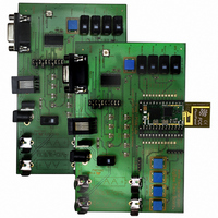
EVAL-PIXIE
Description
KIT EVALUATION PIXIE
Manufacturer
Flexipanel
Series
Pixie™r
Type
802.15.4/Zigbeer
Specifications of EVAL-PIXIE
Frequency
2.4GHz
Interface Type
RS-232
For Use With/related Products
Pixie ZigBee Modules
Lead Free Status / RoHS Status
Lead free / RoHS Compliant
Other names
658-1012
PIXIE-EVAL
ZEVR3
PIXIE-EVAL
ZEVR3


6. Verify that you get a startup message containing
7. Enter the letter F into HyperTerminal to perform a
8. When the device has reset, enter M to turn on
9. You will now specify the function of the input and
10. On the Sleepy End Device, connect jumpers as
Page 4
the version number 1.0-3.5-2.0
This confirms you are running the correct
firmware for this tutorial. If you don’t see 1.0-3.5-
2.0 or higher, contact us to obtain the correct
firmware.
factory reset. This ensures that the firmware is in
the configuration this tutorial expects it to be in.
You will need to press Y to confirm.
Note that when you power up any Switcher unit
except the Coordinator, it will look for a network.
If it can’t find one, it will enter a sleep state. So if
you get no response when you type something,
the device may be sleeping.
button once to wake it up again.
diagnostic messages. These are very useful if
you wish to understand the internal workings of
the Switcher devices.
explained in the document Pixie Switcher
Message Reference DS493.
Note that messages are not normally available
for Pixie Switcher Lite.
hex file is included in the development kit
diagnostic messages enabled and failsafe
disabled for the Fast End Device. You will use
this is in Tutorials 3 and 4.
output pins. Press type E into the HyperTerminal
window, and when prompted, the following
characters:
(That’s three zeroes, not the letter O.) You have
specified the following I/O:
follows: 1A-1B, 2A-2B, 3A-3B, 5A-5B, 6A-6B, 7A-
Endpoint (EP)
DIFC PXSC=1.0-3.5-2.0 (Coordinator)
DIFC PLFE=1.0-3.5-2.0 (Sleepy End Device)
TLD00M0T
25-Jun-07
1
2
3
4
5
6
7
8
Function
Toggle switch (T)
Latching switch (L)
Time delay input (D)
Output, initially off (0)
Output, initially off (0)
Time delay setpoint input (M)
Output, initially off (0)
Toggle switch (T)
Pixie Eval Kit DS482-11
However, an alternate
The messages are
, e.g.:
Press the bind
with
© FlexiPanel Ltd
11. Power up the Sleepy End Device. If you have
12. Repeat steps 2 to 8 for the Sleepy End Device.
13. You will now specify the function of the input and
14. Enter W repeatedly until you get the message:
Note
correspond to the circuit that the Pixie Switcher is
connected to.
product specific and you would normally execute
them at the factory during product manufacture.
Joining
The rest of the tutorial does not require the serial
connections, but you may wish to leave them
connected to read the diagnostic messages out of
interest.
The following steps are one-time only and would
normally be done on-site at the time the equipment is
installed by the customer or technician.
8A, 10A-10B. Note this is slightly different from
the coordinator board.
two serial ports, connect the second to the board;
if not, just swap over the connector from the first
as needed.
output pins. Enter E and, when prompted, the
following characters:
(That’s zero-one.) Remember you may need to
wake it by pressing the Bind button first. You
have specified the following I/O:
You have specified that you want the device to
sleep and wake up every 2 seconds to check
for messages. If any of the EP1 – EP3 or the
Bind switch change state, the device will wake
immediately.
connected to EP1 – EP3, no wakeup would be
required at all.)
Endpoint (EP)
Patents apply and/or pending
that
TLT01TUU
DWKI WkUp=04
1
2
3
4
5
6
7
8
input
All the steps to this point are
Function
Toggle switch (T)
Latching switch (L)
Toggle switch (T)
Output, initially off (0)
Output, initially on (1)
Toggle switch (T)
Unassigned (U)
Unassigned (U)
and
(If you have only inputs
output
www.FlexiPanel.com
settings
must
Related parts for EVAL-PIXIE
Image
Part Number
Description
Manufacturer
Datasheet
Request
R

Part Number:
Description:
ENERCHIP CC EVAL KIT
Manufacturer:
Cymbet Corporation
Datasheet:

Part Number:
Description:
BOARD EVAL FOR AD976
Manufacturer:
Analog Devices Inc
Datasheet:

Part Number:
Description:
BOARD EVAL FOR ADXL345
Manufacturer:
Analog Devices Inc
Datasheet:

Part Number:
Description:
ENERCHIP CC SEH EVAL KIT
Manufacturer:
Cymbet Corporation
Datasheet:

Part Number:
Description:
ENERCHIP EP ENERGY HARVEST EVAL
Manufacturer:
Cymbet Corporation
Datasheet:

Part Number:
Description:
EVAL BOARD FOR TW6864-LB2-GR
Manufacturer:
Intersil
Datasheet:
Part Number:
Description:
EVAL BOARD FOR TW8816-LB3-GR
Manufacturer:
Intersil
Datasheet:
Part Number:
Description:
EVAL BOARD FOR TW8817-TA3-GRS
Manufacturer:
Intersil
Datasheet:

Part Number:
Description:
EVALUATION MODULE FOR ADUM4160
Manufacturer:
Analog Devices Inc
Datasheet:

Part Number:
Description:
BOARD EVALUATION ADCMP581BCP
Manufacturer:
Analog Devices Inc
Datasheet:
Part Number:
Description:
BOARD EVALUATION ADM1041
Manufacturer:
Analog Devices Inc
Datasheet:

Part Number:
Description:
EVAL BOARD FOR STM32F107VCT
Manufacturer:
STMicroelectronics
Datasheet:
Part Number:
Description:
BOARD EVAL FOR AD1954
Manufacturer:
Analog Devices Inc
Datasheet:
Part Number:
Description:
BOARD EVAL FOR AD1955
Manufacturer:
Analog Devices Inc
Datasheet:

Part Number:
Description:
BOARD EVAL FOR AD7655
Manufacturer:
Analog Devices Inc
Datasheet: