AMMP-6530-BLK Avago Technologies US Inc., AMMP-6530-BLK Datasheet
AMMP-6530-BLK
Specifications of AMMP-6530-BLK
Available stocks


Related parts for AMMP-6530-BLK


AMMP-6530-BLK Summary of contents
Page 1
... Intended applica- tions include microwave radios, 802.16, VSAT, and satellite receivers. Since this one mixer can cover several bands, the AMMP-6530 can reduce part inventory. The integrated mixer eliminates complex tuning and assembly processes typically required by hybrid (discrete-FET or diode) mixers ...
Page 2
... Input Port Power at 1dB gain compression point, Plo=+10 dBm NF Noise Figure Notes: 2. Small/Large signal data measured in a fully de-embedded test fixture form T 3. Specifications are derived from measurements in a 50Ω test environment. AMMP-6530 RF Specifications in Drain Pumped Test Configuration ≥+10 dBm 25° -1.0V, P =50 Ω) A ...
Page 3
... AMMP-6530 Typical Performance under Gate Pumped Down Conversion Operation (T = 25° -1V 50Ω drain IF1 -1V IF2 NC 5 gate 4 Note: The external 90 hybrid coupler is from M/A-COM: PN 2032-6344-00. Frequency is 1.0 – 2.0 GHz -10 -15 -20 -25 -30 -35 -40 USB(dB) LSB(dB) -45 - FREQUENCY (GHz) Figure 1. Conversion Gain with IF terminated for High Side Conversion LO=+10 dBm, IF=1 GHz ...
Page 4
... AMMP-6530 Typical Performance under Gate Pumped Down Conversion Operation (T = 25° -1V, Z =50Ω -10 -15 Conv. Gain (dB) Return Loss (dB) - FREQUENCY (GHz) Figure 7. Conversion Gain and Match vs. IF Frequency. RF=20 GHz, LO=10 dBm -10 -15 - FREQUENCY (GHz) Figure 9. RF & LO Return Loss. LO=10 dBm. ...
Page 5
... AMMP-6530 Typical Performance under Gate Pumped Up Conversion Operation (T = 25° -1V, Z =50Ω gate 3 LSB IF2 2 NC USB 1 IF1 8 0 USB (dB) -5 LSB (dB) -10 -15 -20 -25 -30 -35 -40 -45 - FREQUENCY (GHz) Figure 11. Up-conversion Gain with IF terminated for Low Side Conversion. LO=+5 dBm, IF=+5 dBm, IF=1 GHz. ...
Page 6
... AMMP-6530 Typical Performance under Drain Pumped Down Conversion Operation (T = 25° -1V 50Ω drain IF1 -1V IF2 NC 5 gate 4 Note: The external 90 hybrid coupler is from M/A-COM: PN 2032-6344-00. Frequency is 1.0 – 2.0 GHz -10 -15 -20 -25 -30 -35 -40 USB (dB) -45 LSB (dB) - FREQUENCY (GHz) Figure 15. Conversion Gain with IF terminated for Low Side Conversion ...
Page 7
... Please note that the image rejection and isolation performance is dependent on the selection of the low frequency quadrature hybrid. The performance specification of the low frequency quadrature hybrid as well as the phase balance and VSWR of the interface to the AMMP-6530 will affect the overall mixer perfor- mance drain ...
Page 8
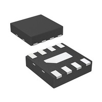
... AMMP XXXX A 8 YWWDNN 7 Front View Symbol A B 0.114 [2.9] 0.011 [0.28] 0.018 [0.46 0.126 [3.2] 0.059 [1.5] 0.100 [2.54] 0.029 [0.75] 5 0.100 [2.54] 0.016 [0.40] 0.093 [2.36] Back View Notes Indicates Pin 1 2. Dimensions are in inches [millimeters] 3. All Grounds must be soldered to PCB RF Ground Figure 23 ...
Page 9
... Recommended SMT Attachment for 5x5 Package Figure 24a. Suggested PCB Land Pattern and Stencil Layout Recommended SMT Attachment The AMMP Packaged Devices are compatible with high volume surface mount PCB assembly processes. The PCB material and mounting pattern, as defined in the data sheet, optimizes RF performance and is strongly recommended. An electronic drawing of the land pattern is available upon request from Avago Sales & ...
Page 10
Manual Assembly 1. Follow ESD precautions while handling packages. 2. Handling should be along the edges with tweezers. 3. Recommended attachment is conductive solder paste. Please see recommended solder reflow profile. Con- ductive epoxy is not recommended. Hand soldering is ...
Page 11
... Carrier Tape and Pocket Dimensions Device Orientation (Top View) Part Number Ordering Information Devices Part Number per Container AMMP-6530-BLK 10 AMMP-6530-TR1 100 AMMP-6530-TR2 500 For product information and a complete list of distributors, please go to our web site: Avago, Avago Technologies, and the A logo are trademarks of Avago Technologies in the United States and other countries. ...