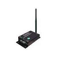
X09-009PKI-RA Digi International, X09-009PKI-RA Datasheet - Page 16

X09-009PKI-RA
Manufacturer Part Number
X09-009PKI-RA
Description
MOD RF 900MHZ 19.2K RS232/485 IN
Manufacturer
Digi International
Series
XStream™r
Specifications of X09-009PKI-RA
Function
Transceiver, FHSS
Modulation Or Protocol
FHSS, FSK
Frequency
900MHz
Applications
ISM
Interface
RS-232, RS-485
Sensitivity
-110dBm
Power - Output
20dBm (100mW)
Data Rate - Maximum
10 kbps
Voltage - Supply
7 V ~ 18 V
Package / Case
Module
Wireless Frequency
900 MHz
Interface Type
SMA
Modulation
FHSS
Operating Temperature Range
- 40 C to + 85 C
Lead Free Status / RoHS Status
Lead free / RoHS Compliant
Features
-
Lead Free Status / Rohs Status
Lead free / RoHS Compliant
Other names
Q4542190
© 2006 MaxStream, Inc. Confidential & Proprietary
XStream‐PKG‐R™ RS‐232/485 RF Modem – Product Manual v5.x00 [2006.02.24]
Note: If serial data exists in the DI buffer while the modem is in
Receive Mode, the UART data will be transmitted after the modem is
finished receiving the RF data and has returned to Idle Mode.
3.2.3. Receive Mode
3.2.4. Sleep Modes
If the modem detects RF data while in Idle Mode, the modem transitions into Receive Mode to
receive RF packets. Once a packet is received, the modem checks the CRC to ensure that the
data was transmitted without error. If the CRC data bits on the incoming packet are invalid, the
packet is discarded. If the CRC is valid, the packet proceeds to the DO Buffer.
The modem returns to Idle Mode when valid RF data is no longer detected or after an error is
detected in the received RF data.
Figure 3.6. Data Reception Sequence
Refer to the Addressing section [p41] of the
RF Communication Modes chapter for more information
regarding address recognition.
Sleep Modes enable the XStream Modem to operate at minimal power consumption when not in
use. Three Sleep Mode options are available:
For the modem to transition into Sleep Mode, the modem must have a non-zero SM (Sleep Mode)
parameter and one of the following must occur:
1.
2.
In Sleep Mode, the modem will not transmit or receive data until the modem first transitions to
Idle Mode. All Sleep Modes are enabled and disabled using SM Command. Transitions into and
out of Sleep Modes are triggered by various mechanisms as shown in the table below.
Table 3.2. Summary of Sleep Mode Configurations
Sleep Mode
Setting
Pin Sleep
(SM = 1)
Serial Port Sleep
(SM = 2)
Cyclic Sleep
(SM = 3-8)
For more information about Sleep Modes, refer to the individual commands listed in “Related Commands”
column of the table. The SM command is central to all Sleep Mode configurations.
• Pin Sleep (Host Controlled)
• Serial Port Sleep (Wake on Serial Port activity)
• Cyclic Sleep (Wake on RF activity)
The modem is idle (no data transmission or reception) for a user-defined period of time
[Refer to the ST (Time before Sleep) command].
SLEEP pin is asserted (only for Pin Sleep option).
Transition into
Sleep Mode
A microcontroller can shut down and wake
modems by asserting (high) SLEEP pin.
Note: The modem will complete a
transmission or reception before activating
Pin Sleep.
Automatic transition to Sleep Mode occurs
after a user-defined period of inactivity (no
transmitting or receiving of data). The
period of activity is defined using the ST
(Time before Sleep) Command.
Automatic transition to Sleep Mode occurs
in cycles as defined by the SM (Sleep
Mode) Command.
Note: The cyclic sleep time interval must be
shorter than the “Wake-up Initializer Timer”
(set by LH Command).
Transition out of
Sleep Mode
De-assert SLEEP pin. SM
When serial byte is
received on the DI pin.
After the cyclic sleep
time interval elapses.
Note: Modem can be
forced into Idle Mode
if PW (Pin Wake-up)
Command is issued.
Related
Commands
SM, ST
SM, ST, HT, LH,
PW
Typical Power
Consumption
6 mA
25 mA
6 mA
when sleeping
16


