X09-009PKI-RA Digi International, X09-009PKI-RA Datasheet - Page 6
X09-009PKI-RA
Manufacturer Part Number
X09-009PKI-RA
Description
MOD RF 900MHZ 19.2K RS232/485 IN
Manufacturer
Digi International
Series
XStream™r
Specifications of X09-009PKI-RA
Function
Transceiver, FHSS
Modulation Or Protocol
FHSS, FSK
Frequency
900MHz
Applications
ISM
Interface
RS-232, RS-485
Sensitivity
-110dBm
Power - Output
20dBm (100mW)
Data Rate - Maximum
10 kbps
Voltage - Supply
7 V ~ 18 V
Package / Case
Module
Wireless Frequency
900 MHz
Interface Type
SMA
Modulation
FHSS
Operating Temperature Range
- 40 C to + 85 C
Lead Free Status / RoHS Status
Lead free / RoHS Compliant
Features
-
Lead Free Status / Rohs Status
Lead free / RoHS Compliant
Other names
Q4542190


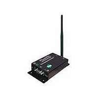
Figure 1.1. Front View
Figure 1.2. Back View
Figure 1.3. DIP Switch Settings
© 2006 MaxStream, Inc. Confidential & Proprietary
XStream‐PKG‐R™ RS‐232/485 RF Modem – Product Manual v5.x00 [2006.02.24]
1.1a.
Power
Switch
1.2a.
DIP Switch
1.1b. I/O &
Power LEDs
1.3. External Interface
1.2b.
Config Switch
1.1c. DB‐9
Serial Port
1.2c.
Antenna Port
1.1d. Power
Connector
1.1a. Power Switch
1.1b. I/O & Power LEDs
1.1c. Serial Port (DB-9 Connector)
1.1d. Power Connector
1.2a. DIP Switch
1.2b. Config (Configuration) Switch
1.2c. Antenna Port
Port is a 50Ω RF signal connector for connecting to an external
antenna. The connector type is RPSMA (Reverse Polarity SMA) female.
Move the Power Switch to the on (up) position to power the
Interface Board. DIP Switch [1.2a] settings are only read
during a power-up sequence.
The LED indicators visualize diagnostic status information. The
modem’s status is represented as follows:
Standard female DB-9 (RS-232) DCE connector – This connector
can be also used for RS-485 and RS-422 connections.
7-18 VDC Power Connector (Center positive, 5.5/2.1mm) – Power
can also be supplied through Pin 9 of the DB-9 Serial Port.
The DIP Switch automatically configures the XStream RF Modem
to operate in different modes. Each time the modem is powered-
on, intelligence inside the XIB-R interface board (inside the
modem) programs the modem according to the positions of the
DIP Switch. [See figure below for DIP Switch settings]
NOTE: In cases where AT Commands should not be sent each time
the RF Modem is powered-on, the processor must be disabled by
populating J7 on the interface board inside the modem [p21].
The Configuration Switch provides an alternate way to enter “AT
Command Mode”. To enter “AT Command Mode” at the RF
modem’s default baud rate, hold the Configuration Switch down
while powering on the modem using the Power Switch [1.1a].
Yellow (top LED) = Serial Data Out (to host)
Green (middle) = Serial Data In (from host)
Red (bottom) = Power/TX Indicator (Red light is on when
powered, off briefly during RF transmission)
The connector has threads on the outside of a
barrel and a male center conductor.
Refer to table in the “Automatic
DIP Switch Configurations” [p19]
section for more information about
configurations triggered by the
DIP Switch.
6
Related parts for X09-009PKI-RA
Image
Part Number
Description
Manufacturer
Datasheet
Request
R

Part Number:
Description:
KIT DEV FOR 900MHZ 9600BPS 100MW
Manufacturer:
Digi International/Maxstream
Datasheet:
Part Number:
Description:
MOD RF 900MHZ 9600BPS W/RPSMA
Manufacturer:
Digi International/Maxstream
Datasheet:
Part Number:
Description:
MOD RF 900MHZ 9600BPS W/WIRE ANT
Manufacturer:
Digi International/Maxstream
Datasheet:
Part Number:
Description:
MOD RF 900MHZ 19.2K W/RPSMA CONN
Manufacturer:
Digi International/Maxstream
Datasheet:
Part Number:
Description:
MOD RF TX 900MHZ 9600BPS W/RPSMA
Manufacturer:
Digi International/Maxstream
Datasheet:
Part Number:
Description:
MOD RF TX 900MHZ 19.2K W/RPSMA
Manufacturer:
Digi International/Maxstream
Datasheet:
Part Number:
Description:
MODULE XSTREAM RF OEM 900MHZ
Manufacturer:
Digi International/Maxstream
Datasheet:
Part Number:
Description:
MOD RF 900MHZ 19.2K W/WIRE ANT
Manufacturer:
Digi International/Maxstream
Datasheet:

Part Number:
Description:
WiFi / 802.11 Modules & Development Tools 900 MHz - XStream 19200 BAUD
Manufacturer:
Digi International
Datasheet:
Part Number:
Description:
WiFi / 802.11 Modules & Development Tools 900 MHz - Xstream 9600 BAUD
Manufacturer:
Digi International
Datasheet:

Part Number:
Description:
IC ARM MICROPROCESSOR 177BGA
Manufacturer:
Digi International
Datasheet:
Part Number:
Description:
DIGI CONNECT 4MB FLASH 8MB RAM
Manufacturer:
Digi International
Datasheet:

Part Number:
Description:
ME 8MB SDRAM 2MB FLASH SINGLE
Manufacturer:
Digi International
Datasheet:
Part Number:
Description:
ME 8MB SDRAM 2MB FLASH SINGLE
Manufacturer:
Digi International
Datasheet:

Part Number:
Description:
MODULE 9P 8MB SDRAM 4MB FLASH
Manufacturer:
Digi International/Maxstream
Datasheet: