MRF89XA-I/MQ Microchip Technology, MRF89XA-I/MQ Datasheet - Page 139
MRF89XA-I/MQ
Manufacturer Part Number
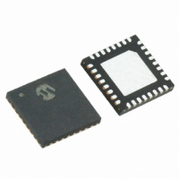
MRF89XA-I/MQ
Description
TXRX ISM SUB-GHZ ULP 32QFN
Manufacturer
Microchip Technology
Specifications of MRF89XA-I/MQ
Package / Case
32-WFQFN Exposed Pad
Frequency
863MHz ~ 870MHz, 902MHz ~ 928MHz, 950MHz ~ 960MHz
Data Rate - Maximum
200kbps
Modulation Or Protocol
FSK, OOK
Applications
ISM
Power - Output
12.5dBm
Sensitivity
-113dBm
Voltage - Supply
2.1 V ~ 3.6 V
Current - Receiving
3mA
Current - Transmitting
25mA
Data Interface
PCB, Surface Mount
Antenna Connector
PCB, Surface Mount
Operating Temperature
-40°C ~ 85°C
Number Of Receivers
1
Number Of Transmitters
1
Wireless Frequency
863 MHz to 870 MHz, 902 MHz to 928 MHz, 950 MHz to 960 MHz
Interface Type
SPI
Noise Figure
- 112 dBc
Output Power
- 8.5 dBm, + 12.5 dBm
Operating Supply Voltage
2.1 V to 3.6 V
Maximum Operating Temperature
+ 85 C
Mounting Style
SMD/SMT
Maximum Data Rate
256 Kbps
Maximum Supply Current
25 mA
Minimum Operating Temperature
- 40 C
Modulation
FSK
Lead Free Status / RoHS Status
Lead free / RoHS Compliant
Memory Size
-
Lead Free Status / Rohs Status
Lead free / RoHS Compliant
Available stocks
Company
Part Number
Manufacturer
Quantity
Price
Company:

Part Number:
MRF89XA-I/MQ
Manufacturer:
MICROCHIP
Quantity:
12 000


INDEX
A
Absolute Maximum Ratings .............................................. 107
Architecture Description ...................................................... 20
B
Bit Synchronizer .................................................................... 7
Block Diagrams
C
Channel Filters .................................................................... 16
CLKOUT Output (CLKOUT Pin) ......................................... 16
Configuration Control/Status Register Map ........................ 57
Configuration/Control/Status Register Description ............. 30
Customer Change Notification Service ............................. 137
Customer Support ............................................................. 137
D
DATA Pin ............................................................................ 19
Digital Pin Configuration vs. Chip Mode ............................. 18
E
Electrical Characteristics................................................... 107
Errata .................................................................................... 5
F
Features
Frequency Synthesizer Block ............................................. 16
Frequency Synthesizer Description .................................... 16
FSK Receiver Setting.......................................................... 22
G
General Configuration Register Details .............................. 32
H
Hardware Description ................................................... 11, 97
I
I(t), Q(t) Overview ............................................................... 20
Internet Address................................................................ 137
Interpolation Filter ............................................................... 15
IRQ Pins and Interrupts ...................................................... 19
L
LO Generator ...................................................................... 17
Low Noise Amplifier (with First Mixer)................................. 15
M
Memory Map ....................................................................... 28
Microchip Internet Web Site .............................................. 137
O
OOK Receiver Setting......................................................... 22
© 2010 Microchip Technology Inc.
Detailed....................................................................... 12
MRF89XA Simplified Functional ................................... 8
Power Supply.............................................................. 14
Current Consumption................................................ 108
Digital I/O Pin Input Specifications............................ 109
PLL Parameters AC Characteristics ......................... 109
Receiver AC Characteristics ..................................... 110
SPI Timing Specification ........................................... 111
Switching Times and Procedures ............................. 112
Transmitter AC Characteristics ................................. 111
Digital Data Processing................................................. 7
Preliminary
P
Packaging
Packaging Information ...................................................... 133
Phase-Locked Loop Architecture........................................ 17
Pin Descriptions.................................................................. 13
Pins
PLL Lock Pin ...................................................................... 17
P
R
Read Bytes Sequence ........................................................ 27
Read Register Sequence.................................................... 25
Reader Response............................................................. 138
Receiver Architecture ......................................................... 21
Recommended Operating Conditions............................... 107
Recommended PA Biasing and Output Matching ............ 101
Reference Oscillator Pins (OSC1/OSC2) ........................... 16
Register Map ...................................................................... 57
Registers
OUT
Details....................................................................... 133
CLKOUT ............................................................... 17, 23
DATA .......................................................................... 19
OSC1.......................................................................... 16
OSC2.......................................................................... 16
PLOCK ....................................................................... 17
Reset .......................................................................... 15
RFIO ..................................................................... 11, 15
Bit Rate Set Register (BRSREG) ............................... 34
Clock Output Control Register (CLKOUTREG) .......... 53
Data and Modulation Configuration Register
FIFO Configuration Register (FIFOCREG)................. 35
FIFO CRC Configuration Register (FCRCREG)......... 56
FIFO Transmit and Receive Interrupt Request
FIFO Transmit PLL and RSSI Interrupt Request
Filter Configuration Register (FILCREG).................... 45
Floor Threshold Control Register (FLTHREG) ........... 35
Frequency Deviation Control Register (FDEVREG)... 34
General Configuration Register (GCONREG) ............ 32
Node Address Set Register (NADDSREG) ................ 54
OOK Configuration Register (OOKCREG) ................. 49
P1 Counter Set Register (P1CREG) .......................... 36
P2 Counter Set Register (P2CREG) .......................... 38
Packet Configuration Register (PKTCREG) ............... 55
Payload Configuration Register (PLOADREG) .......... 54
Polyphase Filter Configuration Register
Power Amplifier Control Register (PACREG)............. 39
R1 Counter Set Register (R1CREG) .......................... 36
R2 Counter Set Register (R2CREG) .......................... 37
Reserved Register (RESVREG)................................. 48
RSSI Status Read Register (RSTSREG) ................... 48
RSSI Threshold Interrupt Request Configuration
S1 Counter Set Register (S1CREG) .......................... 37
S2 Counter Set Register (S2CREG) .......................... 38
SYNC Control Register (SYNCREG) ......................... 47
SYNC Value First Byte
SYNC Value Fourth Byte
and I
(DMODREG) ...................................................... 33
Configuration Register (FTXRXIREG)................ 40
Configuration Register (FTPRIREG) .................. 42
(PFCONREG)..................................................... 46
Register (RSTHIREG) ........................................ 44
Configuration Register (SYNCV32REG) ............ 50
Configuration Register (SYNCV07REG) ............ 51
DD
vs. PA Setting .......................... 124, 15, 14, 17
MRF89XA
DS70622B-page 139
Related parts for MRF89XA-I/MQ
Image
Part Number
Description
Manufacturer
Datasheet
Request
R

Part Number:
Description:
Ultra-low Power, Integrated Ism Band Sub-ghz Transceiver
Manufacturer:
Microchip Technology Inc.
Datasheet:
Part Number:
Description:
Manufacturer:
Microchip Technology Inc.
Datasheet:
Part Number:
Description:
Manufacturer:
Microchip Technology Inc.
Datasheet:
Part Number:
Description:
Manufacturer:
Microchip Technology Inc.
Datasheet:
Part Number:
Description:
Manufacturer:
Microchip Technology Inc.
Datasheet:
Part Number:
Description:
Manufacturer:
Microchip Technology Inc.
Datasheet:
Part Number:
Description:
Manufacturer:
Microchip Technology Inc.
Datasheet:
Part Number:
Description:
Manufacturer:
Microchip Technology Inc.
Datasheet:
Part Number:
Description:
Manufacturer:
Microchip Technology Inc.
Datasheet: