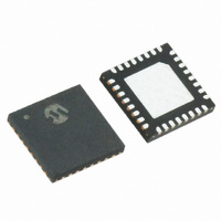
MRF89XA-I/MQ Microchip Technology, MRF89XA-I/MQ Datasheet - Page 70

MRF89XA-I/MQ
Manufacturer Part Number
MRF89XA-I/MQ
Description
TXRX ISM SUB-GHZ ULP 32QFN
Manufacturer
Microchip Technology
Specifications of MRF89XA-I/MQ
Package / Case
32-WFQFN Exposed Pad
Frequency
863MHz ~ 870MHz, 902MHz ~ 928MHz, 950MHz ~ 960MHz
Data Rate - Maximum
200kbps
Modulation Or Protocol
FSK, OOK
Applications
ISM
Power - Output
12.5dBm
Sensitivity
-113dBm
Voltage - Supply
2.1 V ~ 3.6 V
Current - Receiving
3mA
Current - Transmitting
25mA
Data Interface
PCB, Surface Mount
Antenna Connector
PCB, Surface Mount
Operating Temperature
-40°C ~ 85°C
Number Of Receivers
1
Number Of Transmitters
1
Wireless Frequency
863 MHz to 870 MHz, 902 MHz to 928 MHz, 950 MHz to 960 MHz
Interface Type
SPI
Noise Figure
- 112 dBc
Output Power
- 8.5 dBm, + 12.5 dBm
Operating Supply Voltage
2.1 V to 3.6 V
Maximum Operating Temperature
+ 85 C
Mounting Style
SMD/SMT
Maximum Data Rate
256 Kbps
Maximum Supply Current
25 mA
Minimum Operating Temperature
- 40 C
Modulation
FSK
Lead Free Status / RoHS Status
Lead free / RoHS Compliant
Memory Size
-
Lead Free Status / Rohs Status
Lead free / RoHS Compliant
Available stocks
Company
Part Number
Manufacturer
Quantity
Price
Company:
Part Number:
MRF89XA-I/MQ
Manufacturer:
MICROCHIP
Quantity:
12 000
3.4.8
The effect of the f
OOK modes:
3.4.8.1
In FSK mode, the f
FDVAL<7:0> bits (FDEVREG<7:0>), sets sampling fre-
quencies on the receiver. The user should program the
right values to make it consistent with the frequency
deviation of the FSK signal that is received.
3.4.8.2
The frequency deviation f
sets the sampling rate of the RSSI block. It is therefore
necessary to set f
frequency, IF2, of 100 kHz:
3.4.9
The FSK demodulator provides data polarity informa-
tion based on the relative phase of the input I and Q sig-
nals at the baseband. Its outputs can be fed to the Bit
Synchronizer to recover the timing information. The
user can use the raw, unsynchronized, output of the
FSK demodulator in Continuous mode.
The FSK demodulator of the MRF89XA operates effec-
tively for FSK signals with a modulation index greater
than or equal to two, as shown in Equation 3-13.
FIGURE 3-11:
DS70622B-page 70
MRF89XA
f
FDVAL<7:0> = 00000011
dev
RSSI
(dB)
= IF2 = 100 kHz
f
FSK DEMODULATOR
dev
FSK RX Mode
OOK RX Mode
SETTING IN RECEIVE MODE
dev
dev
setting is different for FSK and
OOK DEMODULATOR OVERVIEW
dev
to the recommended low-IF
dev
setting as configured by
, as described previously,
Zoom
OOKTHPV<2:0>
Period as defined in
OOKTHSV<2;0>
Decay in dB as defined in
Preliminary
EQUATION 3-13:
3.4.10
The OOK demodulator performs a comparison of the
RSSI output and a threshold value. Three different
threshold modes are available, which can be pro-
grammed through the OOKTYP<1:0> bits (DMO-
DREG<4:3>).
The recommended mode of operation is the “Peak”
Threshold mode, as illustrated in Figure 3-11.
In Peak Threshold mode, the comparison threshold
level is the peak value of the RSSI, reduced by 6 dB. In
the absence of an input signal or during the reception
of a logical ‘0’, the acquired peak value is decremented
by one based on the step value of the OOKTHSV<2:0>
bits (OOKCREG<7:5>) for every period value based on
OOKTHPV<2:0> bits (OOKCREG<4:2>).
When the RSSI output is null for a long time (for exam-
ple, after a long string of zeros is received, or if no
transmitter is present), the peak threshold level will
continue falling until it reaches the “Floor Threshold”
that is programmed through the FTOVAL<7:0> bits
(FLTHREG<7:0>).
The default settings of the OOK demodulator lead to
the performance stated in Section 5.0 “Electrical
Characteristics”.
Fixed 6dB difference
OOK DEMODULATOR
β
=
© 2010 Microchip Technology Inc.
------------------ -
BRVAL
2
''Peak -6 dB'' Threshold
''Floor'' threshold defined by
FTOVAL<7:0>
Noise floor of
receiver
•
f
dev
≥
2
Time


