MC13201FC Freescale Semiconductor, MC13201FC Datasheet - Page 25
MC13201FC
Manufacturer Part Number
MC13201FC
Description
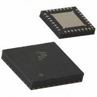
IC TXRX RF 2.4GHZ 32-QFN
Manufacturer
Freescale Semiconductor
Datasheet
1.MC13201FC.pdf
(28 pages)
Specifications of MC13201FC
Frequency
2.4GHz
Data Rate - Maximum
250kbps
Modulation Or Protocol
802.15.4
Applications
AMR, HID, HVAC, ISM
Power - Output
-27dBm ~ 3dBm
Sensitivity
-91dBm
Voltage - Supply
2 V ~ 3.4 V
Current - Receiving
37mA
Current - Transmitting
30mA
Data Interface
PCB, Surface Mount
Antenna Connector
PCB, Surface Mount
Operating Temperature
-40°C ~ 85°C
Package / Case
32-QFN
Operating Supply Voltage
2.7 V
Mounting Style
SMD/SMT
Minimum Operating Temperature
- 40 C
Operating Temperature (min)
-40C
Operating Temperature (max)
85C
Operating Temperature Classification
Industrial
Lead Free Status / RoHS Status
Lead free / RoHS Compliant
Memory Size
-
Lead Free Status / Rohs Status
Lead free / RoHS Compliant
Available stocks
Company
Part Number
Manufacturer
Quantity
Price

Company:
Part Number:
MC13201FCR2
Manufacturer:
NEC
Quantity:
1 588
Part Number:
MC13201FCR2
Manufacturer:
MOTOROLA/摩托罗拉
Quantity:
20 000


Table 10
8.7
CT_Bias is a useful signal for interface with external RF components. It must be enabled via the ct_bias_en
control bit, and then its state is determined first by the selected RF mode and then by the active state of the
radio, i.e., whether a TX or RX operation is active:
Table 11
Note that the output state is also defined in Idle, Hibernate, and Doze state as well as RX and TX operation.
Freescale Semiconductor
Bit
14
13
12
•
•
ct_bias_en
ct_bias_inv
RF_switch_mode
Single Port Operation - In this mode, the CT_Bias can be used to establish the proper DC bias
voltage to a balun depending on the RX state versus TX state as described in
Port
VDDA for TX and is at ground for RX.
Dual Port Operation - In this mode, the CT_Bias can be used as a control signal to enable a LNA
or PA or to determine the direction of an antenna switch as described in
Operation. In dual port operation, ct-bias_inv is used to control the sense of the output control, i.e.,
CT_Bias can be active high or active low for TX and vice-versa for RX.
Designation
defines the CT_Bias output state depending on control bits and operation mode of the modem.
summarizes the operation of the RF interface control bits.
RF Control Output CT_Bias
Operation. Note that in single port operation, the ct_bias_inv has no effect and CT_Bias is at
Mode
RX
RX
RX
RX
RX
TX
TX
TX
Default
0
0
0
Table 11. CT_Bias Output vs. Register Settings
CT_Bias_en
1 = CT_Bias enabled. Output state is defined by
0 = CT_Bias disabled. Output state is tri-stated.
The output state of CT_Bias under varying conditions is defined in
has effect for dual port operation.
1 = CT_Bias inverted.
0 = CT_Bias not inverted
1= Single Port Mode selected where RF switch is active and RFIN_M and RFIN_P and
bidirectional signals.
0 = Dual Port Mode selected where RFIN_M and RFIN_P are inputs only and PAO_P
and PAO_N are separate outputs.
(This is default operation).
1
1
1
0
1
1
1
1
Table 10. RF Interface Control Bits
MC13201 Technical Data, Rev. 1.3,
RF_switch_mode
X
1
1
0
1
1
1
0
CT_Bias_inv
Operation
X
0
1
0
0
0
1
0
Table
0
0
0
Hi-Z
1
1
1
1
11.
CT_Bias
Section 8.5.2, “Dual Port
Section 8.5.1, “Single
Table
11. This bit only
25
Related parts for MC13201FC
Image
Part Number
Description
Manufacturer
Datasheet
Request
R

Part Number:
Description:
Manufacturer:
Freescale Semiconductor, Inc
Datasheet:
Part Number:
Description:
Manufacturer:
Freescale Semiconductor, Inc
Datasheet:
Part Number:
Description:
Manufacturer:
Freescale Semiconductor, Inc
Datasheet:
Part Number:
Description:
Manufacturer:
Freescale Semiconductor, Inc
Datasheet:
Part Number:
Description:
Manufacturer:
Freescale Semiconductor, Inc
Datasheet:
Part Number:
Description:
Manufacturer:
Freescale Semiconductor, Inc
Datasheet:
Part Number:
Description:
Manufacturer:
Freescale Semiconductor, Inc
Datasheet:
Part Number:
Description:
Manufacturer:
Freescale Semiconductor, Inc
Datasheet:
Part Number:
Description:
Manufacturer:
Freescale Semiconductor, Inc
Datasheet:
Part Number:
Description:
Manufacturer:
Freescale Semiconductor, Inc
Datasheet:
Part Number:
Description:
Manufacturer:
Freescale Semiconductor, Inc
Datasheet:
Part Number:
Description:
Manufacturer:
Freescale Semiconductor, Inc
Datasheet:
Part Number:
Description:
Manufacturer:
Freescale Semiconductor, Inc
Datasheet:
Part Number:
Description:
Manufacturer:
Freescale Semiconductor, Inc
Datasheet:
Part Number:
Description:
Manufacturer:
Freescale Semiconductor, Inc
Datasheet: