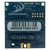
AC4486-5M Laird Technologies, AC4486-5M Datasheet - Page 34

AC4486-5M
Manufacturer Part Number
AC4486-5M
Description
TXRX 868MHZ 3V TTL 5MW RS232
Manufacturer
Laird Technologies
Series
AeroCommr
Specifications of AC4486-5M
Frequency
868MHz
Data Rate - Maximum
115.2kbps
Modulation Or Protocol
FSK
Applications
AMR, Gaming Devices, Inventory Tracking
Power - Output
5mW
Sensitivity
-100dBm
Voltage - Supply
3.3V
Current - Receiving
30mA
Current - Transmitting
40mA
Data Interface
Connector, 2 x 10 Header
Antenna Connector
MMCX
Operating Temperature
-40°C ~ 85°C
Package / Case
Module
Board Size
49 mm x 42 mm x 5 mm
Output Power
5 mW
Antenna
External MMCX Connector
Frequency Rf
869.65MHz
Transmit Power
5mW
Interface Type
Serial
Rohs Compliant
Yes
Lead Free Status / RoHS Status
Lead free / RoHS Compliant
Memory Size
-
Lead Free Status / Rohs Status
Lead free / RoHS Compliant
Available stocks
Company
Part Number
Manufacturer
Quantity
Price
Company:
Part Number:
AC4486-5M
Manufacturer:
Laird Technologies Wireless M2
Quantity:
135
AC4486 Specifications
4.6.19 W ite Digital Outputs
The Host issues this command to write both digital output lines to particular states.
Host Command:
Transceiver Response:
4.6.20 W ite DAC
The Host issues this command to write DA Out to a particular voltage. NOTE: DA Out is an unbuffered,
high impedance output and must be buffered by the OEM Host when used. The transceiver uses a
PWM (Pulse Width Modulator) to generate the analog voltage. The theory behind PWM is that a binary
pulse is generated with a fixed duty cycle and rate. As such, this pin toggles between High and Low.
This signal is filtered via an onboard R-C circuit and an analog voltage is generated. Duty Cycle
specifies the ratio of time in one cycle that the pulse spends High proportionate to the amount of time it
spends Low. So, with a duty cycle of 50% (80h), the pulse is High 50% of the time and Low 50% of the
time; therefore the analog voltage would be half of 3.3V or 1.15V. A broad filter has been implemented
on the transceiver and there is no advantage to using a slower update period. Generally, a faster
update period is preferred.
Host Command:
Transceiver Response:
01/21/05
Byte 1 = CCh
Byte 2 = 23h
Byte 3 = Data1
Where:
Data1 = bit 0 – GO0, bit 1 – GO1
Byte 1 = CCh
Byte 2 = Data1
Where:
Data1 = Data1 from Host command
Byte 1 = CCh
Byte 2 = 24h
Byte 3 = Data1
Byte 4 = Data2
Where:
Data1 = Update Period where: T
Data2 = Duty Cycle where: Vout = (Data2 / FFh) * 3.3V
Byte 1 = CCh
Byte 2 = Data1
Byte 3 = Data2
Where:
Data1 = Data1 from Host Command
Data2 = Data2 from Host Command
r
r
Update
= (255 * (Data1 + 1)) / 14.7256
+06
34


