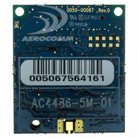
AC4486-5M Laird Technologies, AC4486-5M Datasheet - Page 9

AC4486-5M
Manufacturer Part Number
AC4486-5M
Description
TXRX 868MHZ 3V TTL 5MW RS232
Manufacturer
Laird Technologies
Series
AeroCommr
Specifications of AC4486-5M
Frequency
868MHz
Data Rate - Maximum
115.2kbps
Modulation Or Protocol
FSK
Applications
AMR, Gaming Devices, Inventory Tracking
Power - Output
5mW
Sensitivity
-100dBm
Voltage - Supply
3.3V
Current - Receiving
30mA
Current - Transmitting
40mA
Data Interface
Connector, 2 x 10 Header
Antenna Connector
MMCX
Operating Temperature
-40°C ~ 85°C
Package / Case
Module
Board Size
49 mm x 42 mm x 5 mm
Output Power
5 mW
Antenna
External MMCX Connector
Frequency Rf
869.65MHz
Transmit Power
5mW
Interface Type
Serial
Rohs Compliant
Yes
Lead Free Status / RoHS Status
Lead free / RoHS Compliant
Memory Size
-
Lead Free Status / Rohs Status
Lead free / RoHS Compliant
Available stocks
Company
Part Number
Manufacturer
Quantity
Price
Company:
Part Number:
AC4486-5M
Manufacturer:
Laird Technologies Wireless M2
Quantity:
135
AC4486 Specifications
3. Specifications
3.1 I
The AC4486 has a simple interface that allows OEM Host communications with the transceiver. The
table below shows the connector pin numbers and associated functions. The I/O direction is with
respect to the transceiver. All outputs are 3.3VDC levels and inputs are 5VDC TTL (with the exception of
AC4486-500 transceivers which are 3.3V inputs). All inputs are weakly pulled High and may be left
floating during normal operation.
I = Input to the transceiver
1
01/21/05
Pin
10
11
12
13
14
15
16
17
18
19
20
When ordered with a RS-485 interface.
1
2
3
4
5
6
7
8
9
NTERFACE
Type
GND
PWR
PWR
GND
I/O
I/O
O
O
O
O
O
O
O
O
I
I
I
I
I
I
I
I
RS485 B (Invert)
S
RS485 A (True)
Command/Data
Signal Name
9600_BAUD
IGNAL
Hop Frame
UP_RESET
IN_RANGE
DA Out
VCC1
VCC2
AD In
GO0
GND
GO1
RSSI
GND
RXD
CTS
TXD
RTS
GI0
GI1
D
EFINITIONS
1
1
O = Output from the transceiver
Table 1 – Pin Definitions
Generic Output pin
Transmitted data out of the transceiver
Noninverted RS-485 representation of serial data
Data input to the transceiver
Mirror image of RS-485 A
Generic Input pin
Signal Ground
Pulses Low when the transceiver is hopping.
Clear to Send – Active Low when the transceiver is ready to accept data for transmission.
Request to Send – When enabled in EEPROM, the OEM Host can take this High when it
is not ready to accept data from the transceiver. NOTE: Keeping RTS High for too long
can cause data loss.
Generic Output pin
AC4486-5: 3.3 – 5.5V, ±50mV ripple
AC4486-500: 3.3 – 5.5V, ±50mV ripple
AC4486-5: 3.3 – 5.5V, ±50mV ripple
AC4486-500: 3.3V ±3%, ±100mV ripple
9600_BAUD – When pulled logic Low and then applying power or resetting, the
transceiver’s serial interface is forced to a 9600, 8, N, 1 rate. To exit, transceiver must be
reset or power-cycled with 9600_Baud logic High.
Received Signal Strength - An analog output giving an instantaneous indication of
received signal strength. Only valid while in Receive Mode.
Generic Input pin
RESET – Controlled by the AC4486 for power-on reset if left unconnected. After a Stable
power-on reset, a logic High pulse will reset the transceiver.
Signal Ground
When logic Low, the transceiver interprets Host data as command data. When logic
High, the transceiver interprets Host data as transmit data.
10 bit Analog Data Input
10 bit Analog Data Output
In Range – Active Low when a Client transceiver is in range of a Server on same Channel with the
same System ID. Always Low on a Server.
Function
9


