ATA5824-PLQW Atmel, ATA5824-PLQW Datasheet - Page 86
ATA5824-PLQW
Manufacturer Part Number
ATA5824-PLQW
Description
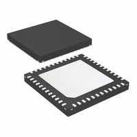
IC TXRX UHF ASK/FSK 48QFN
Manufacturer
Atmel
Datasheet
1.ATA5824-PLQW.pdf
(98 pages)
Specifications of ATA5824-PLQW
Frequency
433 ~ 435MHz; 866 ~ 870MHz
Data Rate - Maximum
20kbps
Modulation Or Protocol
ASK, FSK
Applications
RKE, TPM, Security Systems
Power - Output
10dBm
Sensitivity
-116dBm
Voltage - Supply
2.15 V ~ 3.6 V or 4.4 V ~ 5.25 V
Current - Receiving
10.5mA
Current - Transmitting
10.5mA
Data Interface
PCB, Surface Mount
Antenna Connector
PCB, Surface Mount
Operating Temperature
-40°C ~ 105°C
Package / Case
48-VQFN Exposed Pad, 48-HVQFN, 48-SQFN, 48-DHVQFN
Lead Free Status / RoHS Status
Lead free / RoHS Compliant
Memory Size
-
Available stocks
Company
Part Number
Manufacturer
Quantity
Price
Company:

Part Number:
ATA5824-PLQW
Manufacturer:
ATMEL
Quantity:
3 500
Part Number:
ATA5824-PLQW
Manufacturer:
ATMEL/爱特梅尔
Quantity:
20 000


18. Electrical Characteristic: Battery Application
All parameters refer to GND and are valid for T
T
otherwise specified. Microcontroller interface current I
86
amb
*) Type means: A = 100% tested, B = 100% correlation tested, C = Characterized on samples, D = Design parameter
10.10
10.11
10.1
10.2
10.3
10.4
10.5
10.6
10.7
10.8
10.9
No.
10
= 25°C. Application according to
Parameters
Battery Application
Supported voltage
range (every mode
except high power TX
mode)
Supported voltage
range (high power TX
mode)
Supply voltage for
microcontroller
interface
Supply current
OFF mode
Current in IDLE mode
on pin VS1 and VS2
Supply current
IDLE mode
Current in RX mode
on pin VS1and VS2
Supply current
RX mode
Current during
T
and VS2
Current in
RX polling mode on
pin VS1 and VS2
Supply current
RX polling mode
ATA5823/ATA5824
Startup_PLL
on pin VS1
Test Conditions
battery application
PWR_H = GND
battery application
PWR_H = AVCC
V
_OFF =
I
V
CLK enabled
CLK disabled
CLK enabled
V
CLK enabled
V
OFF_VSINT
VS1,2
VS1
VS1
VS1
Figure 3-1 on page 6
I
Poll
= V
= V
= V
I
= V
OFF_VS1,2
=
I
------------------------------------------------------------------------------------------------------------------------------------------------------------------------------------------------------------------------------------------------------------------------------------------------------------ -
VS2
VS2
VS2
IDLE_VS1,2
VSINT
amb
3V
3V
3V
= –40°C to +105°C, V
+
3.6VI
VSINT
T
S
Sleep
has to be added.
or
17, 18
17, 18
17,18,
17, 18
18, 27
17, 18
18, 27
17, 18
18, 27
Figure 5-1 on page
+
Pin
17,
17,
17,
27
27
I
Startup_PLL_VS1,2
T
Sleep
I
Startup_PLL_VS1, 2
VS1
+
V
V
I
T
IDLE_VS1, 2
I
Symbol
VS1
VS1
RX_VS1, 2
Startup_PLL
V
I
= V
I
I
S_IDLE
I
S_OFF
S_Poll
S_RX
VSINT
, V
, V
VS2
VS2
VS2
8. f
= 2.15V to 3.6V typical values at V
T
Startup_PLL
I
I
I
I
I
IDLE_VS1,2
RX_VS1,2
Startup_PLL_VS1,2
TX_VS1,2
FD1,2_VS1,2
+
RF
T
Startup_Sig_Proc
= 315.0 MHz/ 433.92 MHz/868.3 MHz unless
Min.
2.15
2.15
2.7
or
or
or
+
I
RX_VS1,2
or
I
Typ.
10.5
S_IDLE =
330
270
I
8.8
S_RX
2
+
T
I
VS1
VS2
Bitcheck
Poll
= I
T
I
IDLE_VS1,2
RX_VS1, 2
= I
Startup_Sig_Proc
Max.
5.25
11.5
350
570
490
3.6
3.6
14
P
+ I
VSINT
VS1
+ I
+ I
VSINT
Unit
= V
VSINT
mA
mA
nA
µA
µA
V
V
V
4829D–RKE–06/06
+
VS2
T
Bit check
= 3V and
Type*
C
A
A
A
A
A
B
A
Related parts for ATA5824-PLQW
Image
Part Number
Description
Manufacturer
Datasheet
Request
R

Part Number:
Description:
RF Transceiver RF Data Control Duplex Trans.
Manufacturer:
Atmel
Datasheet:

Part Number:
Description:
Manufacturer:
Atmel
Datasheet:

Part Number:
Description:
DEV KIT FOR AVR/AVR32
Manufacturer:
Atmel
Datasheet:

Part Number:
Description:
INTERVAL AND WIPE/WASH WIPER CONTROL IC WITH DELAY
Manufacturer:
ATMEL Corporation
Datasheet:
Part Number:
Description:
Low-Voltage Voice-Switched IC for Hands-Free Operation
Manufacturer:
ATMEL Corporation
Datasheet:
Part Number:
Description:
MONOLITHIC INTEGRATED FEATUREPHONE CIRCUIT
Manufacturer:
ATMEL Corporation
Datasheet:
Part Number:
Description:
AM-FM Receiver IC U4255BM-M
Manufacturer:
ATMEL Corporation
Datasheet:
Part Number:
Description:
Monolithic Integrated Feature Phone Circuit
Manufacturer:
ATMEL Corporation
Datasheet:
Part Number:
Description:
Multistandard Video-IF and Quasi Parallel Sound Processing
Manufacturer:
ATMEL Corporation
Datasheet:
Part Number:
Description:
High-performance EE PLD
Manufacturer:
ATMEL Corporation
Datasheet:
Part Number:
Description:
8-bit Flash Microcontroller
Manufacturer:
ATMEL Corporation
Datasheet:
Part Number:
Description:
2-Wire Serial EEPROM
Manufacturer:
ATMEL Corporation
Datasheet: