AC4790-200A-485 Laird Technologies, AC4790-200A-485 Datasheet - Page 26
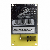
AC4790-200A-485
Manufacturer Part Number
AC4790-200A-485
Description
TXRX 900MHZ 3.3-5.5V FHSS 200MW
Manufacturer
Laird Technologies
Series
AeroCommr
Specifications of AC4790-200A-485
Frequency
902MHz ~ 928MHz
Data Rate - Maximum
115.2kbps
Modulation Or Protocol
FHSS, FSK
Applications
AMR, Fire & Security Alarms, Telemetry
Power - Output
5mW ~ 200mW
Sensitivity
-110dBm
Voltage - Supply
3.3V, 5V
Current - Transmitting
68mA
Data Interface
Connector, 2 x 10 Header
Antenna Connector
On-Board, Chip
Operating Temperature
-40°C ~ 85°C
Package / Case
Module
Wireless Frequency
900 MHz
Interface Type
20-pin mini connector
Board Size
49 mm x 42 mm x 5 mm
Modulation
FHSS, FSK
Security
1 byte System ID, DES
Operating Voltage
3.3 V to 5.5 V
Output Power
200 mW
Antenna
Integral and External Dipole
Lead Free Status / RoHS Status
Contains lead / RoHS non-compliant
Memory Size
-
Current - Receiving
-
Lead Free Status / Rohs Status
Lead free / RoHS Compliant


2 2
H A R D W A R E I N T E R F A C E
prevent the transceiver from sending it data by disabling RTS (logic High). Once RTS is enabled (logic Low), the
transceiver can send packets to the OEM Host as they are received.
Note: Leaving RTS disabled for too long can cause data loss once the transceiver’s 256 byte receive buffer fills up.
T e s t / 9 6 0 0 B a u d
When pulled logic Low before applying power or resetting, the transceiver’s serial interface is forced to a 9600, 8-N-1
(8 data bits, No parity, 1 stop bit). To exit, the transceiver must be reset or power-cycled with Test pin logic High. This
pin is used to recover transceivers from unknown baud rates only. It should not be used in normal operation. Instead
the transceiver Interface Baud Rate should be programmed to 9600 baud if that rate is desired for normal operation.
The Test/9600 pin should be used for recovery purposes only as some functionality is disabled in this mode.
R S S I
Received Signal Strength Indicator is used by the OEM Host as an indication of instantaneous signal strength at the
receiver. The OEM Host must calibrate RSSI without an RF signal being presented to the receiver. Calibration is
accomplished by following the steps listed below.
1) Power up only one transceiver in the coverage area.
2) Measure the RSSI signal to obtain the minimum value with no other signal present.
3) Power up another transceiver and begin sending data from that transceiver to the transceiver being measured.
Make sure the two transceivers are separated by approximately ten feet.
4) Measure the peak RSSI, while the transceiver is in Session, to obtain a maximum value at full signal strength.
As RSSI is only valid when the local transceiver is receiving an RF packet from a remote transceiver, instantaneous
RSSI can be very tricky to use. Therefore, the transceiver stores the most recent valid RSSI value. The OEM Host
issues the Report Last Good RSSI command to request that value. Additionally, validated RSSI can be obtained from
Receive Packet and Send Data Complete API commands and from the Probe command. Validated RSSI is not
available at the RSSI pin. The following equation approximates the RSSI curve:
I N S T A N T A N E O U S R S S I
V A L I D A T E D R S S I
Signal Strength (dBm) = (-46.9
×
VRSSI )
–
53.9
Related parts for AC4790-200A-485
Image
Part Number
Description
Manufacturer
Datasheet
Request
R

Part Number:
Description:
TXRX 900MHZ 3.3-5.5V FHSS 200MW
Manufacturer:
Laird Technologies
Datasheet:

Part Number:
Description:
TXRX 900MHZ 3.3V FHSS 1W
Manufacturer:
Laird Technologies
Datasheet:

Part Number:
Description:
TXRX 900MHZ 3.3-5.5V FHSS 200MW
Manufacturer:
Laird Technologies
Datasheet:
Part Number:
Description:
TXRX 900MHZ 3.3V FHSS 1W
Manufacturer:
Laird Technologies
Datasheet:

Part Number:
Description:
TXRX 900MHZ 3.3-5.5V FHSS 200MW
Manufacturer:
Laird Technologies
Datasheet:

Part Number:
Description:
Bluetooth Serial Module Development Kit
Manufacturer:
Laird Technologies
Part Number:
Description:
BLUETOOTH MODULE DEVELOPMENT KIT
Manufacturer:
Laird Technologies
Part Number:
Description:
Bluetooth 2.0 AT Data Module, Internal Antenna Development Kit
Manufacturer:
Laird Technologies

Part Number:
Description:
BLUETOOTH EVAL BOARD BTM511
Manufacturer:
Laird Technologies
Datasheet:

Part Number:
Description:
Bluetooth / 802.15.1 Modules & Development Tools BLUETTH Multimed MODLE, No ANT DEVKIT
Manufacturer:
Laird Technologies
Datasheet:

Part Number:
Description:
CHOKE COMMON MODE 110 OHMS SMD
Manufacturer:
Laird Technologies
Datasheet: