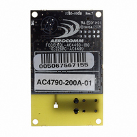
AC4790-200A-485 Laird Technologies, AC4790-200A-485 Datasheet - Page 37

AC4790-200A-485
Manufacturer Part Number
AC4790-200A-485
Description
TXRX 900MHZ 3.3-5.5V FHSS 200MW
Manufacturer
Laird Technologies
Series
AeroCommr
Specifications of AC4790-200A-485
Frequency
902MHz ~ 928MHz
Data Rate - Maximum
115.2kbps
Modulation Or Protocol
FHSS, FSK
Applications
AMR, Fire & Security Alarms, Telemetry
Power - Output
5mW ~ 200mW
Sensitivity
-110dBm
Voltage - Supply
3.3V, 5V
Current - Transmitting
68mA
Data Interface
Connector, 2 x 10 Header
Antenna Connector
On-Board, Chip
Operating Temperature
-40°C ~ 85°C
Package / Case
Module
Wireless Frequency
900 MHz
Interface Type
20-pin mini connector
Board Size
49 mm x 42 mm x 5 mm
Modulation
FHSS, FSK
Security
1 byte System ID, DES
Operating Voltage
3.3 V to 5.5 V
Output Power
200 mW
Antenna
Integral and External Dipole
Lead Free Status / RoHS Status
Contains lead / RoHS non-compliant
Memory Size
-
Current - Receiving
-
Lead Free Status / Rohs Status
Lead free / RoHS Compliant
Control 1
Interface Timeout
RF Packet Size
CTS On
CTS Off
Max Power
Parity
Destination ID
System ID
RS-485 DE
MAC ID
Original Max
Power
Parameter
0x56
0x58
0x5B
0x5C
0x5D
0x63
0x6F
0x70
0x76
0x7F
0x80
0x8E
EEPROM
Address
T a b l e 1 2 : E E P R O M P a r a m e t e r s
1
1
1
1
1
1
1
6
1
1
6
1
(Bytes)
Length
www.lairdtech.com\wireless
0x02
0xFF
0x01
0x80
0x01
0xFF
0x00
0xFE
0x00
0x60
0xE3,
0xFF
0x00
0xFF
0x00
0xFF
0xE3,
0xFF
0x00
0xFF
Range
-
-
-
-
-
-
-
-
0x43
0x04
0x80
0xD2
0xAC
Set
Production
& can vary
0xFF
0x01
0xFF
Set
Production
and can vary
Default
in
in
Description
Settings are:
bit-7: Laird Technology Use Only
bit-6: Laird Technology Use Only
bit-5: Laird Technology Use Only
bit-4: Auto Destination
bit-3: Laird Technology Use Only
bit-2: RTS Enable
bit-1: Duplex
bit-0: Auto Config
Specifies a byte gap timeout, used in conjunction with RF
Packet Size to determine when a packet coming over the
interface is complete (0.5 ms per increment).
Used in conjunction with Interface Timeout; specifies the
maximum size of an RF packet.
CTS will be deasserted (High) when the transmit buffer
contains at least this many characters.
Once CTS has been deasserted, CTS will be reasserted
(Low) when the transmit buffer is contains this many or less
characters.
Used to increase/decrease the output power. The
transceivers are shipped at maximum allowable power.
0xE3 = Enable Parity
0xFF = Disable Parity
Note: Enabling parity cuts throughput and the interface
buffer size in half.
Specifies destination for RF packets
Similar to network password. Radios must have the same
system ID to communicate with each other.
0xE3 = GO0 is active Low DE for control of external RS-485
hardware
0xFF = Disable RS-485 DE
Factory programmed unique IEEE MAC address.
Copy of original max power EEPROM setting. This address
may be referenced but should not be modified.
0 = Use destination address
1 = Use auto destination
0 = Ignore RTS
1 = Transceiver obeys RTS
0 = Use EEPROM values
1 = Auto Configure values
0 = Half Duplex
1 = Full Duplex
E E P R O M P A R A M E T E R S
3 3


