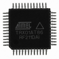
AT86RF211DAI Atmel, AT86RF211DAI Datasheet - Page 12

AT86RF211DAI
Manufacturer Part Number
AT86RF211DAI
Description
IC RF TXRX FSK 400-950MHZ 48TQFP
Manufacturer
Atmel
Datasheet
1.AT86RF211DB-433LT.pdf
(19 pages)
Specifications of AT86RF211DAI
Frequency
400MHz ~ 950MHz
Data Rate - Maximum
100kbps
Modulation Or Protocol
FSK
Applications
ISM
Power - Output
7dBm ~ 12dBm
Sensitivity
-107dBm
Voltage - Supply
2.4 V ~ 3.6 V
Data Interface
PCB, Surface Mount
Antenna Connector
PCB, Surface Mount
Operating Temperature
-40°C ~ 85°C
Package / Case
48-TQFP Exposed Pad, 48-eTQFP, 48-HTQFP, 48-VQFP
Lead Free Status / RoHS Status
Contains lead / RoHS non-compliant
Memory Size
-
Current - Transmitting
-
Current - Receiving
-
Set-Up of a Transceiver
and Initialization of a
"Sleep" Procedure
Relevant Registers
Procedure to Put a
Transceiver to Sleep
12
AT86RF211 (TRX01)
All wake-up parameters are set-up as wanted at the beginning of the application by writ-
ing into the relevant registers. Following registers are used for set-up:
•
•
•
When a correct message is received, Data field (if used) is stored into Wake-up Data
Register (WUD), and the STATUS register contents the relevant flags, length of
received Data field (if variable) & measured data rate.
These registers are fully described in the datasheet.
Note: WPER is from 10 ms to 328s, WL1 from 1 ms to 1024 ms, WL2 from 0 to 31xWL1.
These 3 parameters are process (and piece to piece) dependent (±20%).
parameters can be measured on the production bench and "calibrated" by software (the ±20%
dispersion is reduced and all the devices have the same timeslots).
The registers must be filled properly by the microcontroller.
Once the AT86RF211 is set-up as wanted (examples will be given at chapter “How to
Wake-up (a) Distant Device(s)?” on page 13), the microcontroller should:
•
•
•
•
Starting a wake-up cycle will:
•
•
•
•
•
Wake-up Control Register (WUC): definition of WPER, WL1, WL2, Address/Data
fields properties + others
Wake-up Data Rate Register (WUR): definition of wake-up message expected data
rate + others
Wake-up Address Register (WUA): definition of device's address
set-up the transceiver in PDN mode since sleep mode is a sub-mode of PDN mode,
so CTRL1[31] = '0'.
set WUEN = CTRL1[26] = '1'
set WUE = WUC[31] = '1'
–
go to sleep, waiting for an external interrupt: WAKEUP pin when valid message
received by AT86RF211.
deactivate WAKEUP pin and WAKEUP of STAT register,
reset the message error flag MSGERR of STAT register in MSGTST,
reset the extracted data rate MSGMRATE of STAT register,
reset the wake-up data register WUD,
reset the wake-up data message length MSGDATL of STAT register.
at this moment, the wake-up cycle begins
2186A–WIRE–08/02
The time


