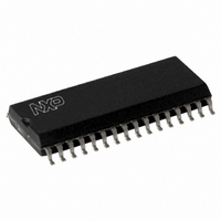
SLRC40001T/OFE,112 NXP Semiconductors, SLRC40001T/OFE,112 Datasheet - Page 65

SLRC40001T/OFE,112
Manufacturer Part Number
SLRC40001T/OFE,112
Description
IC I.CODE SLRC400 READER 32-SOIC
Manufacturer
NXP Semiconductors
Series
I-Coder
Datasheets
1.SLRC40001TOFE112.pdf
(130 pages)
2.SLRC40001TOFE112.pdf
(132 pages)
3.SLRC40001TOFE112.pdf
(101 pages)
Specifications of SLRC40001T/OFE,112
Rf Type
Read Only
Frequency
13.56MHz
Features
ISO15693, ISO18000-3
Package / Case
32-SOIC (0.300", 7.50mm Width)
Product
RFID Readers
Operating Temperature Range
- 25 C to + 85 C
Lead Free Status / RoHS Status
Lead free / RoHS Compliant
Lead Free Status / RoHS Status
Lead free / RoHS Compliant, Lead free / RoHS Compliant
Other names
568-1124-5
935269551112
SLRC400
SLRC41TOFED
935269551112
SLRC400
SLRC41TOFED
- Current page: 65 of 130
- Download datasheet (689Kb)
E²PROM Byte
Philips Semiconductors
I•CODE Reader IC
6.3.2
During production test, the Start Up Register Initialisation File is initialised with the values shown in the table
below. With each power up these values are written into the SL RC400 register during the Initialising Phase.
Address
1C
1D
2C
2D
1A
1B
1E
1F
2A
2B
2E
2F
10
11
12
13
14
15
16
17
18
19
20
21
22
23
24
25
26
27
28
29
SHIPMENT CONTENT OF START UP REGISTER INITIALISATION FILE
Address
Reg.
1A
1B
1C
1D
1E
2A
2B
2C
2D
2E
10
11
12
13
14
15
16
17
18
19
1F
20
21
22
23
24
25
26
27
28
29
2F
Table 6-5: Shipment Content of Start Up Configuration File
Value
2C
0C
FE
3F
3F
3F
8B
FF
3E
0B
00
58
05
00
00
00
54
68
00
41
00
00
08
00
00
00
00
02
00
02
00
00
Page: free for user
TxControl: Transmitter pins TX1 and TX2 switched off, bridge driver configuration,
modulator driven from internal digital circuitry
CwConductance: Source resistance of TX1 and TX2 to minimum.
ModGsCfg: Source resistance of TX1 and TX2 at the time of Modulation, to determine
the modulation index
CoderControl: Selects the bit coding mode and the framing during transmission
ModWidth: Pulse width for “used code (1 out of 256, RZ or 1 out of 4)” pulse coding is
set to standard configuration.
ModWidthSOF Pulse width of SOF
PreSet17
Page: free for user
RxControl1: Amplifier gain is maximum.
DecoderControl: A bit-collision always evaluates to HIGH in the data bit stream.
BitPhase: BitPhase is set to standard configuration.
RxThreshold: MinLevel and CollLevel are set to maximum.
PreSet1D
RxControl2: Use Q-clock for the receiver, ‘Automatic Receiver Off’ is switched on,
decoder is driven from internal analog circuitry.
ClockQControl: Automatic Q-clock Calibration’ is switched on.
Page: free for user
RxWait: Frame Guard Time is set to six bit clocks.
ChannelRedundancy: Channel Redundancy is set according to I●CODE1.
CRCPresetLSB: CRC-Preset value is set according to I●CODE1.
CRCPresetMSB: CRC-Preset value is set according to I●CODE1.
PreSet25
SIGOUTSelect: Pin SIGOUT is set to LOW.
PreSet27
Page: free for user
FIFOLevel: WaterLevel: FIFO buffer warning level is set to standard configuration.
TimerClock: TPreScaler is set to standard configuration, timer unit restart function is
switched off.
TimerControl: Timer is started at the end of transmission, stopped at the beginning of
reception.
TimerReload: TReloadValue: the timer unit preset value is set to standard configuration
IRQPinConfig: Pin IRQ is set to high impedance.
PreSet2E
PreSet2F
65
Product Specification Rev. 3.1 August 2004
Description
SL RC400
Related parts for SLRC40001T/OFE,112
Image
Part Number
Description
Manufacturer
Datasheet
Request
R
Part Number:
Description:
NXP Semiconductors designed the LPC2420/2460 microcontroller around a 16-bit/32-bitARM7TDMI-S CPU core with real-time debug interfaces that include both JTAG andembedded trace
Manufacturer:
NXP Semiconductors
Datasheet:

Part Number:
Description:
NXP Semiconductors designed the LPC2458 microcontroller around a 16-bit/32-bitARM7TDMI-S CPU core with real-time debug interfaces that include both JTAG andembedded trace
Manufacturer:
NXP Semiconductors
Datasheet:
Part Number:
Description:
NXP Semiconductors designed the LPC2468 microcontroller around a 16-bit/32-bitARM7TDMI-S CPU core with real-time debug interfaces that include both JTAG andembedded trace
Manufacturer:
NXP Semiconductors
Datasheet:
Part Number:
Description:
NXP Semiconductors designed the LPC2470 microcontroller, powered by theARM7TDMI-S core, to be a highly integrated microcontroller for a wide range ofapplications that require advanced communications and high quality graphic displays
Manufacturer:
NXP Semiconductors
Datasheet:
Part Number:
Description:
NXP Semiconductors designed the LPC2478 microcontroller, powered by theARM7TDMI-S core, to be a highly integrated microcontroller for a wide range ofapplications that require advanced communications and high quality graphic displays
Manufacturer:
NXP Semiconductors
Datasheet:
Part Number:
Description:
The Philips Semiconductors XA (eXtended Architecture) family of 16-bit single-chip microcontrollers is powerful enough to easily handle the requirements of high performance embedded applications, yet inexpensive enough to compete in the market for hi
Manufacturer:
NXP Semiconductors
Datasheet:
Part Number:
Description:
The XA-S3 device is a member of Philips Semiconductors? XA(eXtended Architecture) family of high performance 16-bitsingle-chip microcontrollers
Manufacturer:
NXP Semiconductors
Datasheet:

Part Number:
Description:
The NXP BlueStreak LH75401/LH75411 family consists of two low-cost 16/32-bit System-on-Chip (SoC) devices
Manufacturer:
NXP Semiconductors
Datasheet:

Part Number:
Description:
The NXP LPC3130/3131 combine an 180 MHz ARM926EJ-S CPU core, high-speed USB2
Manufacturer:
NXP Semiconductors
Datasheet:

Part Number:
Description:
The NXP LPC3141 combine a 270 MHz ARM926EJ-S CPU core, High-speed USB 2
Manufacturer:
NXP Semiconductors

Part Number:
Description:
The NXP LPC3143 combine a 270 MHz ARM926EJ-S CPU core, High-speed USB 2
Manufacturer:
NXP Semiconductors

Part Number:
Description:
The NXP LPC3152 combines an 180 MHz ARM926EJ-S CPU core, High-speed USB 2
Manufacturer:
NXP Semiconductors

Part Number:
Description:
The NXP LPC3154 combines an 180 MHz ARM926EJ-S CPU core, High-speed USB 2
Manufacturer:
NXP Semiconductors

Part Number:
Description:
Standard level N-channel enhancement mode Field-Effect Transistor (FET) in a plastic package using NXP High-Performance Automotive (HPA) TrenchMOS technology
Manufacturer:
NXP Semiconductors
Datasheet:


