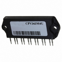
CPV363M4K Vishay, CPV363M4K Datasheet

CPV363M4K
Specifications of CPV363M4K
VS-CPV363M4K
VS-CPV363M4K
VSCPV363M4K
VSCPV363M4K
Available stocks
Related parts for CPV363M4K
CPV363M4K Summary of contents
Page 1
... Junction-to-Case, each IGBT, one IGBT in conduction JC R (DIODE) Junction-to-Case, each diode, one diode in conduction JC R (MODULE) Case-to-Sink, flat, greased surface CS Wt Weight of module Document Number: 93604 CPV363M4K Short Circuit Rated UltraFast IGBT 90° 125°C, Supply Voltage 360Vdc Max. -40 to +150 300 (0.063 in. (1.6mm) from case) 5-7 lbf• ...
Page 2
... CPV363M4K Electrical Characteristics @ T Parameter V Collector-to-Emitter Breakdown Voltage (BR)CES Temp. Coeff. of Breakdown Voltage (BR)CES J V Collector-to-Emitter Saturation Voltage CE(on) V Gate Threshold Voltage GE(th Temp. Coeff. of Threshold Voltage GE(th Forward Transconductance fe I Zero Gate Voltage Collector Current CES V Diode Forward Voltage Drop FM I Gate-to-Emitter Leakage Current ...
Page 3
... Collector-to-Emitter Voltage (V) CE Fig Typical Output Characteristics Document Number: 93604 1 f, Frequency (KHz) (Load Current = I of fundamental) RMS 100 150 15V 0 Fig Typical Transfer Characteristics CPV363M4K 0° ° tor = ula tio . ted V o lta 150 50V CC 5µs PULSE WIDTH Gate-to-Emitter Voltage (V) GE www ...
Page 4
... CPV363M4K ase T em pera ture (° Fig Maximum Collector Current vs. Case Temperature 0.50 1 0.20 0.10 0.05 0. 0.01 SINGLE PULSE ( THE RMAL RES PO NSE) 0.01 0.0000 1 0.0001 Fig Maximum IGBT Effective Transient Thermal Impedance, Junction-to-Case Document Number: 93604 3 15V PULSE WIDTH 2 ...
Page 5
... R , Gate Resistance (Ohm Gate Resistance ( G Fig Typical Switching Losses vs. Gate Resistance Document Number: 93604 20 C SHORTED 100 0.1 -60 -40 - Fig Typical Switching Losses vs. CPV363M4K V = 400V 6. Total Gate Charge (nC) G Fig Typical Gate Charge vs. Gate-to-Emitter Voltage 23Ohm 15V 480V 100 120 140 160 ° ...
Page 6
... CPV363M4K 1 23Ohm G ° 150 C J 480V 15V 1.2 GE 0.9 0.6 0.3 0 Collector-to-emitter Current (A) C Fig Typical Switching Losses vs. Collector-to-Emitter Current 100 10 1 0.4 Fig Maximum Forward Voltage Drop vs. Instantaneous Forward Current Document Number: 93604 50° 25° 25°C J 0.8 1.2 1.6 2.0 2 ...
Page 7
... I = 12A F 200 100 /µs) f Fig Typical Stored Charge vs. di Document Number: 93604 100 6 1000 100 Fig Typical Recovery Current vs. di /dt f 10000 1000 100 10 100 1000 Fig Typical di /dt f CPV363M4K ° ° . /µ ° ° / /µ /dt vs. di (rec)M www.vishay.com 1000 ...
Page 8
... CPV363M4K 430µF 80% of Vce Fig. 18a - Test Circuit for Measurement off(diode ATE VO LTA . 10 td( on) t1 Fig. 18c - Test Waveforms for Circuit of Fig. 18a, Defining d(on) Document Number: 93604 Same t ype device D.U.T. D.U. (off d(on) r d(off) f Fig. 18b - Test Waveforms for Circuit of Fig. 18a, Defining ...
Page 9
... L 10 00V 50V 60 00µ F 100 V Document Number: 93604 ATE VICE UNDE CURR . D.U.T. CURR D.U. 480V CPV363M4K 480V @25°C C www.vishay.com 9 ...
Page 10
... CPV363M4K Repetitive rating: V =20V; pulse width limited by maximum junction temperature (figure 20 =80%( =20V, L=10µ CES GE Pulse width 80µs; duty factor Pulse width 5.0µs, single shot. 3.91 ( .154) 2X 21.97 (.865 3.94 (.155) 4.06 ± 0.51 (.160 ± .020) 5.08 (.200) 6X WORLD HEADQUARTERS: 233 Kansas St ...
Page 11
... Except as provided in Vishay's terms and conditions of sale for such products, Vishay assumes no liability whatsoever, and disclaims any express or implied warranty, relating to sale and/or use of Vishay products including liability or warranties relating to fitness for a particular purpose, merchantability, or infringement of any patent, copyright, or other intellectual property right. ...


