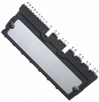
PS21A79 Powerex Inc, PS21A79 Datasheet - Page 3

PS21A79
Manufacturer Part Number
PS21A79
Description
MOD IPM 600V 50A LARGE DIP
Manufacturer
Powerex Inc
Series
DIPIPM™r
Type
IGBTr
Datasheet
1.PS21A79.pdf
(7 pages)
Specifications of PS21A79
Configuration
3 Phase
Current
50A
Voltage
600V
Voltage - Isolation
2500VDC
Package / Case
PCB Module
Dc Collector Current
50A
Collector Emitter Voltage Vces
600V
Power Dissipation Pd
142W
Collector Emitter Voltage V(br)ceo
600V
Operating Temperature Range
-20°C To +100°C
No. Of Pins
42
Lead Free Status / RoHS Status
Lead free / RoHS Compliant
Other names
835-1045
Available stocks
Company
Part Number
Manufacturer
Quantity
Price
Company:
Part Number:
PS21A79
Manufacturer:
QUALCOMM
Quantity:
2 000
Part Number:
PS21A79
Manufacturer:
MITSUBISHI/三菱
Quantity:
20 000
Powerex, Inc., 173 Pavilion Lane, Youngwood, Pennsylvania 15697 (724) 925-7272
PS21A79
Intellimod™ Module
Dual-In-Line Intelligent Power Module
50 Amperes/600 Volts
Electrical and Mechanical Characteristics, T
Characteristics
IGBT Inverter Sector
Collector-Emitter Saturation Voltage
Diode Forward Voltage
Inductive Load Switching Times
Collector-Emitter Cutoff Current
Control Sector
Circuit Current
Fault Output Voltage
Input Current
Short-Circuit Trip Level*
Supply Circuit Undervoltage
Protection
Fault Output Pulse Width**
ON Threshold Voltage
OFF Threshold Voltage
Temperature Output
* Short-Circuit protection is functioning only at the lower arms. Please select the value of the external shunt resistor such that the SC trip level is less than 85A.
**Fault signal is asserted when the lower arm short circuit or control supply under-voltage protective functions operate. The fault output pulse-width t
***When the temperature rises excessively, the controller (MCU) should stop the DIPIPM.
Rev. 08/09
of C
FO
according to the following approximate equation: C
V
V
UV
UV
V
Symbol
V
CE(sat)
t
t
V
UV
UV
I
V
C(on)
C(off)
V
th(on)
th(off)
CES
I
t
t
t
FOH
I
FOL
t
I
SC
FO
on
off
EC
IN
OT
D
FO
rr
DBt
DBr
Dt
Dr
= (12.2 x 10
I
I
C
C
V
-20°C ≤ T
= 50A, T
SC
= 50A, T
V
V
-6
j
I
UFB
UFB
= 0V, F
x t
C
Inductive Load (Upper-Lower Arm)
Applied between U
= 25°C unless otherwise specified
FO
T
= 50A, T
V
At LVIC Temperature = 85°C
j
-V
-V
CC
Total of V
Total of V
V
V
V
V
[F]).
= 25°C, -I
j
Reset Level, T
Reset Level, T
j
V
C
D
D
D
D
= 125°C, V
V
UFS
UFS
Trip Level, T
Trip Level, T
= 25°C, V
V
CE
O
CE
= 300V, V
≤ 100°C, V
= V
= V
= V
= V
SC
U
Terminal Pull-up to 5V by 10kΩ
, V
, V
= V
N
j
= V
DB
DB
DB
DB
C
= 1V, I
= 125°C, V
, V
VFB
VFB
V
FO
P1
P1
CES
CES
C
IN
N
= 15V, V
= 15V, V
= 15V, V
= 15V, V
Test Conditions
-V
-V
D
, W
= 50A, V
= 22nF
D
-V
-V
D
= 5V
, T
PC
PC
FO
= V
, T
C
C
D
= V
VFS
VFS
= V
C
C
N
P
j
≤ 100°C
≤ 100°C
, V
, V
, V
= 15V, R
j
-V
= 125°C
DB
= 1mA
≤ 100°C
≤ 100°C
= 25°C
DB
DB
IN
, V
, V
IN
IN
IN
IN
NC
N1
N1
P
, W
= 15V, V
IN
= 0 ⇔ 5V,
WFB
WFB
= 15V, V
= 5V,
-V
= 5V,
= 0V,
-V
= 0V,
= 15V,
P
= 0V
NC
NC
-V
S
-V
-V
PC,
= 21.5Ω
WFS
WFS
IN
IN
= 5V
= 5V
Min.
85.0
10.0
10.5
10.3
10.8
3.50
1.80
4.9
2.1
0.8
1.0
1.0
—
—
—
—
—
—
—
—
—
—
—
—
—
—
FO
2.40
0.30
0.40
3.00
0.65
3.63
depends on the capacitance value
1.55
1.65
1.70
Typ.
1.8
2.3
1.5
1.4
—
—
—
—
—
—
—
—
—
—
—
—
—
150.0
Max.
2.05
2.10
2.20
0.55
0.55
0.95
12.0
12.5
12.5
13.0
3.76
7.00
7.00
2.0
2.6
2.1
1.0
—
—
—
—
—
10
—
—
Amps
Units
Volts
Volts
Volts
Volts
Volts
Volts
Volts
Volts
Volts
Volts
Volts
Volts
mA
mA
mA
mA
mA
mA
mA
ms
µs
µs
µs
µs
µs
3


