PS21A79 Powerex Inc, PS21A79 Datasheet - Page 6
PS21A79
Manufacturer Part Number
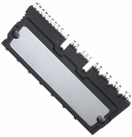
PS21A79
Description
MOD IPM 600V 50A LARGE DIP
Manufacturer
Powerex Inc
Series
DIPIPM™r
Type
IGBTr
Datasheet
1.PS21A79.pdf
(7 pages)
Specifications of PS21A79
Configuration
3 Phase
Current
50A
Voltage
600V
Voltage - Isolation
2500VDC
Package / Case
PCB Module
Dc Collector Current
50A
Collector Emitter Voltage Vces
600V
Power Dissipation Pd
142W
Collector Emitter Voltage V(br)ceo
600V
Operating Temperature Range
-20°C To +100°C
No. Of Pins
42
Lead Free Status / RoHS Status
Lead free / RoHS Compliant
Other names
835-1045
Available stocks
Company
Part Number
Manufacturer
Quantity
Price
Company:

Part Number:
PS21A79
Manufacturer:
QUALCOMM
Quantity:
2 000
Part Number:
PS21A79
Manufacturer:
MITSUBISHI/三菱
Quantity:
20 000


6
Protection Function Timing Diagrams
Powerex, Inc., 173 Pavilion Lane, Youngwood, Pennsylvania 15697 (724) 925-7272
PS21A79
Intellimod™ Module
Dual-In-Line Intelligent Power Module
50 Amperes/600 Volts
Under-Voltage Protection (N-side , UV D )
SENSE VOLTAGE OF R S
Short Circuit Protection (N-side Only with External Shunt Resistor and RC Filter)
OUTPUT CURRENT I C
OUTPUT CURRENT I C
INTERNAL IGBT GATE
CONTROL SUPPLY
FAULT OUTPUT F O
FAULT OUTPUT F O
CONTROL INPUT
CONTROL INPUT
CIRCUIT STATE
b1: Control supply voltage V D rises – After V D level reaches under voltage reset level (UV Dr ), the circuits
b2 : Normal operation – IGBT turns on and carries current.
b3: V D level dips to under voltage trip level (UV Dt ).
b4: All N-side IGBT’s turn off in spite of control input condition.
b5: F O is low for a minimum period determined by the capacitance C FO but continuously during UV period.
b6: V D level reaches UV Dr .
b7: Normal operation – IGBT turns on and carries current.
CIRCUIT STATE
PROTECTION
VOLTAGE V D
a1: Normal operation – IGBT turns on and carries current.
a2: Short circuit current is detected (SC trigger).
a3: All N-side IGBT's gate are hard interrupted.
a4: All N-side IGBT's turn off.
a5: F O output wirh a fixed pulse width (determined by the external capacitance C FO ).
a6: Input "L" – IGBT off.
a7: Input "H" – IGBT on, but during the F O output perid the IGBT will not turn on.
a8: IGBT turns on when L→H signal is input after F O is reset.
PROTECTION
start to operate when next input is applied.
N-SIDE
UV Dr
RESET
a1
b1
a2
SC
UV Dt
SET
a5
b2
a3
SET
a4
b3
b4
SC REFERENCE VOLTAGE
RC CIRCUIT TIME CONSTANT DELAY
a6
b5
RESET
a7
RESET
b6
b7
a8
Rev. 08/09
Related parts for PS21A79
Image
Part Number
Description
Manufacturer
Datasheet
Request
R

Part Number:
Description:
Manufacturer:
Powerex Inc
Datasheet:
Part Number:
Description:
Manufacturer:
Powerex Inc
Datasheet:
Part Number:
Description:
Manufacturer:
Powerex Inc
Datasheet:
Part Number:
Description:
Manufacturer:
Powerex Inc
Datasheet:
Part Number:
Description:
Manufacturer:
Powerex Inc
Datasheet:
Part Number:
Description:
Manufacturer:
Powerex Inc
Datasheet:
Part Number:
Description:
Manufacturer:
Powerex Inc
Datasheet:
Part Number:
Description:
Manufacturer:
Powerex Inc
Datasheet:
Part Number:
Description:
Manufacturer:
Powerex Inc
Datasheet:
Part Number:
Description:
Manufacturer:
Powerex Inc
Datasheet:
Part Number:
Description:
Manufacturer:
Powerex Inc
Datasheet:
Part Number:
Description:
Manufacturer:
Powerex Inc
Datasheet:
Part Number:
Description:
Manufacturer:
Powerex Inc
Datasheet:
Part Number:
Description:
Manufacturer:
Powerex Inc
Datasheet: