PS21A79 Powerex Inc, PS21A79 Datasheet - Page 4
PS21A79
Manufacturer Part Number
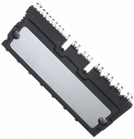
PS21A79
Description
MOD IPM 600V 50A LARGE DIP
Manufacturer
Powerex Inc
Series
DIPIPM™r
Type
IGBTr
Datasheet
1.PS21A79.pdf
(7 pages)
Specifications of PS21A79
Configuration
3 Phase
Current
50A
Voltage
600V
Voltage - Isolation
2500VDC
Package / Case
PCB Module
Dc Collector Current
50A
Collector Emitter Voltage Vces
600V
Power Dissipation Pd
142W
Collector Emitter Voltage V(br)ceo
600V
Operating Temperature Range
-20°C To +100°C
No. Of Pins
42
Lead Free Status / RoHS Status
Lead free / RoHS Compliant
Other names
835-1045
Available stocks
Company
Part Number
Manufacturer
Quantity
Price
Company:

Part Number:
PS21A79
Manufacturer:
QUALCOMM
Quantity:
2 000
Part Number:
PS21A79
Manufacturer:
MITSUBISHI/三菱
Quantity:
20 000


4
Powerex, Inc., 173 Pavilion Lane, Youngwood, Pennsylvania 15697 (724) 925-7272
PS21A79
Intellimod™ Module
Dual-In-Line Intelligent Power Module
50 Amperes/600 Volts
Thermal Characteristics, T
Characteristic
Thermal Resistance Junction to Case
Thermal Resistance Junction to Case
Recommended Conditions for Use
Characteristic
Supply Voltage
Control Supply Voltage
Control Supply Variation
Arm Shoot-through
Blocking Time
PWM Input Frequency
Allowable rms Current*
Minimum Input
Pulse Width
V
* The allowable rms current value depends on the actual application conditions.
**If input signal ON pulse is less than P WIN(on) , the device may not respond.
***The IPM may fail to respond to an ON pulse if the preceeding OFF pulse is less than P WIN(off) .
Delayed Response Against Shorter Input OFF Signal Than P WIN
NC
Variation
50 ≤ I
P
P
ΔV
I
WIN(off)***
WIN(on)
C
j
t
f
DEAD
V
V
V
D
PWM
= 25°C unless otherwise specified
V
≤ 50A
I
C
CC
DB
, ΔV
NC
O
D
≤ 85A
CONTROL INPUT
R
R
DB
**
Symbol
Symbol
th(j-C)D
CURRENT I C
th(j-C)Q
IGBT GATE
INTERNAL
OUTPUT
Solid Line – OFF Pulse Width > P WIN(off) : Turn ON time t1.
Dotted Line – OFF Pulse Width < P WIN(off) : Turn ON time t2.
P-SIDE
Between V
f
f
PWM
N-line Wiring Inductance Less Than 10nH
PWM
13.5 ≤ V
200 ≤ V
Applied between V
For Each Input Signal, T
Applied between P-NU, NV, NW
= 15kHz, PF = 0.8, Sinusoidal PWM,
Applied between V
= 5kHz, PF = 0.8, Sinusoidal PWM,
FWDi Part (Per 1/6 Module)
IGBT Part (Per 1/6 Module)
V
DB
T
T
T
V
V
CC
NC
VFB
C
j
j
CC
CC
≤ 125°C, T
≤ 125°C, T
≤ 18.5V, -20°C ≤ T
-NU, NV, NW (Including Surge)
≤ 100°C, T
≤ 350V, 13.5 ≤ V
-V
= 300V, V
= 300V, V
VFS
t2
, V
Condition
Condition
P1
C
C
WFB
j
-V
D
D
≤ 125°C
≤ 100°C
≤ 100°C
UFB
PC
= 15V,
= 15V,
-V
C
, V
-V
WFS
D
t1
≤ 100°C
(off)
C
UFS
N1
≤ 16.5V,
≤ 100°C,
-V
, P-side only
,
NC
Min.
Min.
13.5
13.0
-5.0
2.0
0.3
3.0
5.0
—
—
-1
—
—
—
0
15.0
15.0
Typ.
300
Typ.
—
—
—
—
—
—
—
—
—
—
—
Max.
Max.
0.88
16.5
18.5
23.6
13.8
1.78
400
5.0
20
—
—
—
—
1
°C/Watt
Arms
Arms
Volts
Volts
Volts
Volts
°C/Watt
V/µs
kHz
Rev. 08/09
µs
µs
µs
µs
Units
Units
Related parts for PS21A79
Image
Part Number
Description
Manufacturer
Datasheet
Request
R

Part Number:
Description:
Manufacturer:
Powerex Inc
Datasheet:
Part Number:
Description:
Manufacturer:
Powerex Inc
Datasheet:
Part Number:
Description:
Manufacturer:
Powerex Inc
Datasheet:
Part Number:
Description:
Manufacturer:
Powerex Inc
Datasheet:
Part Number:
Description:
Manufacturer:
Powerex Inc
Datasheet:
Part Number:
Description:
Manufacturer:
Powerex Inc
Datasheet:
Part Number:
Description:
Manufacturer:
Powerex Inc
Datasheet:
Part Number:
Description:
Manufacturer:
Powerex Inc
Datasheet:
Part Number:
Description:
Manufacturer:
Powerex Inc
Datasheet:
Part Number:
Description:
Manufacturer:
Powerex Inc
Datasheet:
Part Number:
Description:
Manufacturer:
Powerex Inc
Datasheet:
Part Number:
Description:
Manufacturer:
Powerex Inc
Datasheet:
Part Number:
Description:
Manufacturer:
Powerex Inc
Datasheet:
Part Number:
Description:
Manufacturer:
Powerex Inc
Datasheet: