HSDL-9100-024 Avago Technologies US Inc., HSDL-9100-024 Datasheet - Page 10
HSDL-9100-024
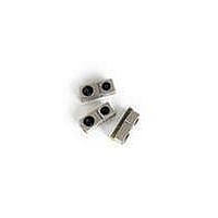
Manufacturer Part Number
HSDL-9100-024
Description
IC PROX SENSOR ANLG OUT REFL SMD
Manufacturer
Avago Technologies US Inc.
Datasheet
1.HSDL-9100-021.pdf
(13 pages)
Specifications of HSDL-9100-024
Sensing Distance
0.197" (5mm)
Sensing Method
Reflective
Current - Collector (ic) (max)
100mA
Current - Dc Forward (if)
100mA
Output Type
Analog
Response Time
6µs, 6µs
Mounting Type
Surface Mount
Package / Case
4-SMD
Operating Temperature
-40°C ~ 85°C
Maximum Operating Temperature
+ 85 C
Minimum Operating Temperature
- 40 C
Proximity Sensor Type
Optical
Proximity Sensor Sensing Distance
5mm
Proximity Sensor Sensing Distance Range
2 to 7mm
Mounting
Surface Mount
Package Type
SMD
Operating Temp Range
-40C to 85C
Operating Temperature Classification
Industrial
Pin Count
4
Lead Free Status / RoHS Status
Lead free / RoHS Compliant
Voltage - Collector Emitter Breakdown (max)
-
Lead Free Status / Rohs Status
Lead free / RoHS Compliant
Available stocks
Company
Part Number
Manufacturer
Quantity
Price
Company:

Part Number:
HSDL-9100-024
Manufacturer:
AVAGO
Quantity:
40 000


Appendix A: HSDL-9100 SMT Assembly Application Note
Recommended Metal solder Stencil Aperture
It is recommended that only a 0.152 mm (0.006 inch) or
a 0.127 mm (0.005 inch) thick stencil be used for solder
paste printing. This is to ensure adequate printed solder
paste volume and no shorting. See Table 1 below the
drawing for combinations of metal stencil aperture and
metal stencil thickness that should be used. Aperture
opening for shield pad is 3.05 mm x 1.1 mm as per land
pattern.
Table 1. Combinations of metal stencil aperture and metal
stencil thickness
Adjacent Land Keep out and Solder Mask Areas
Adjacent land keep out is the maximum space occupied
by the unit relative to the land pattern. There should be
no other SMD components within this area. The minimum
solder resist strip width required to avoid solder bridging
adjacent pads is 0.2mm.It is recommended that two
fiducial crosses be placed at mid length of the pads for
unit alignment. Also do take note that there should not
be any electrical routing with the component placement
compartment.
Note:
Solder Pad, Mask and Metal Stencil
Figure 9. Stencil and PCBA
10
Stencil
thickness,
t (mm)
0.152
0.127
Wet/Liquid Photo-imaginable solder resist/mask is recommended
Solder Mask
Stencil Aperture
Metal stencil for
solder paste printing
1.60+/-0.05
Length,
1.92
l
Aperture size (mm)
PCBA
0.55+/-0.05
0.55+/-0.05
Width,
w
Land Pattern
Recommended land pattern
Figure 11. Solder stencil aperture
Solder / stencil opening for each pad is 2.4mm x0.6mm
Figure 10. Land Pattern
Figure 12. Keep-out area
Dim.
h
Solder Mask
k
l
j
Apertures as per
Land Dimensions
2.1
k
j
4.15
mm
5.5
3.5
11
w
l
7.7
7.1
Mounting Center
Component placement
2.4
l
h
t
Related parts for HSDL-9100-024
Image
Part Number
Description
Manufacturer
Datasheet
Request
R

Part Number:
Description:
EMITTER IR 5MM 875NM
Manufacturer:
Lite-On Electronics
Datasheet:

Part Number:
Description:
ENCODER/DECODER 3/16 8-SOIC
Manufacturer:
Lite-On Electronics
Datasheet:

Part Number:
Description:
PHOTOSENSOR MINI 3V 550NM 6-PLCC
Manufacturer:
Avago Technologies US Inc.

Part Number:
Description:
Infrared Transceiver
Manufacturer:
Avago Technologies US Inc.

Part Number:
Description:
Infrared Transceivers IR Transceiver 115.2Kb/s
Manufacturer:
Lite-On Electronics
Datasheet:

Part Number:
Description:
Infrared Transceivers FIR + RC
Manufacturer:
Avago Technologies US Inc.
Datasheet:

Part Number:
Description:
Manufacturer:
Avago Technologies
Datasheet:

Part Number:
Description:
Manufacturer:
Agilent Technologies, Inc.
Datasheet:
Part Number:
Description:
EMITTER IR FLAT 875NM SHORT LDS
Manufacturer:
Lite-On Electronics
Datasheet:
Part Number:
Description:
EMITTER IR FLAT 875NM LONG LDS
Manufacturer:
Lite-On Electronics
Datasheet:
Part Number:
Description:
Standard LED - SMD Polyled Emmiter Long Leads
Manufacturer:
Lite-On Electronics
Datasheet:

Part Number:
Description:
IC ENCODER/DECODER IRDA 16-SOIC
Manufacturer:
Lite-On Electronics
Datasheet:

Part Number:
Description:
IC ENCODER/DECODER IRDA 16-QFN
Manufacturer:
Lite-On Electronics
Datasheet:
Part Number:
Description:
ENCODER/DECODER 3/16 8-SOIC
Manufacturer:
Lite-On Electronics
Datasheet:
Part Number:
Description:
ENCODER/DECODER 3/16 CLK 16-SOIC
Manufacturer:
Lite-On Electronics
Datasheet: