A16-1NRN Omron, A16-1NRN Datasheet - Page 242
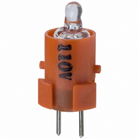
A16-1NRN
Manufacturer Part Number
A16-1NRN
Description
NEON LAMP 110V RED FOR A16
Manufacturer
Omron
Type
Neon Lamp, 110 VoltsACr
Series
A16r
Datasheets
1.M2DA-7001.pdf
(265 pages)
2.A16-1NRN.pdf
(30 pages)
3.A16-2.pdf
(27 pages)
4.A165-CAA.pdf
(17 pages)
Specifications of A16-1NRN
Accessory Type
Neon Lamp Replacement
Supply Voltage
110V
Base Type
Bi-Pin
Colour
Red
Current Rating
1.5mA
Svhc
No SVHC (15-Dec-2010)
Illumination Colour
Red
Operating Lifetime
10000h
Voltage Rating Vac
110V
Average Bulb Life
1000
Color
Red
Illumination
Illuminated
Height
13 mm
Illumination Color
Red
Mounting Style
Snap In
Termination Style
Tabs
Lamp Base Type
Bi-Pin
Rohs Compliant
Yes
Lead Free Status / RoHS Status
Lead free / RoHS Compliant
For Use With/related Products
A16 Series
For Use With
Z1397 - SWTCH KNOB RND 3POS DPDT ILL REDZ1394 - SWTCH KNOB RND 2POS SPDT ILL REDZ1391 - SWTCH KNOB RND 2POS SPDT ILL REDZ1385 - SWITCH KNB RECT 3POS DPDT ILLZ1382 - SWITCH KNB RECT 2POS SPDT ILLZ1379 - SWITCH KNB RECT 2POS SPDT ILLZ1373 - SWITCH KNOB SQ 3-POS DPDT ILLZ1370 - SWITCH KNOB SQ 2-POS SPDT ILLZ1367 - SWITCH KNOB SQ 2-POS SPDT ILLZ1309 - SWITCH PB RND MOM DPDT ILLUM REDZ1305 - SWITCH PB RECT MOM DPDT ILLUMZ1301 - SWITCH PB SQ MOM DPDT ILLUM RED
Lead Free Status / Rohs Status
Lead free / RoHS Compliant
Other names
A161NRN
Z1342
Z1342


A3P
LED Chameleon Models
(The terminal arrangement diagram shows a 1-switch output. Connections to terminals from the lighting block are the same for 2 outputs.)
Chameleon Models
(If using a Switch Guard or Seal Cover, refer to the panel cutout diagrams on page 244.)
A3PJ (Rectangular) Models
Note: 1. n: Number of Units
240
Rectangular A3PJ
model
Square A3PA
model
Wiring
Coloring
Flange
mount
models
Barrier
mount
models
Rated voltage
Terminal Arrangement and Coloring
Panel Cutout
g
Classification
2. Recommended panel thickness: 1 to 5 mm
3. Mount the panel before mounting the Switch Guard.
4. If the panel is to be finished (e.g., coated), make sure that the panel meets the specified dimensions after the coating.
Individual
mounting
(Horizontal)
Multiple
mounting
(Horizontal)
Individual
mounting
(Vertical)
Multiple
mounting
(Vertical)
Individual
mounting
(Horizontal)
Multiple
mounting
(Horizontal)
Individual
mounting
(Vertical)
Multiple
mounting
(Vertical)
LC+
L1–
Green
25±0.1
32±0.1
25±0.1
32±0.1
34
27
34
27
LC+
L2–
Red
32±0.1
25±0.1
32±0.1
1
1
39
1
–
–
1
–
Mounting design
–
+
–
25n±0.5
24 VDC
2
2
26n+6±1
2
32n±0.5
2
33n+6±1
Mount to long mounting plate
(A3PJ-3002) before use.
LC+
L1– and L2–
shorted
Orange
n
n
Mount to long
mounting plate
(A3PJ-3002)
before use.
n
Mount to long
mounting plate
(A3PJ-3002)
before use.
Mount to long
mounting plate
(A3PJ-3002)
before use.
n
30.5±0.3
23.5±0.3
30.5±0.3
30.5±0.3
23.5±0.3
23.5±0.3
23.5±0.3
30.5±0.3
23.5±0.3
30.5±0.3
36.4±0.3
29.4±0.3
25n–1.5±0.3
Panel cutout
25.9n+3.5±0.3
32n–1.5±0.3
32.9n+3.5±0.3
Panel cutout spacing between rows
of Units:
For barrier mount models, refer to
Accessories on page 234.
Panel cutout spacing between rows
of Units:
of Units:
(Dotted line indicates the position
of each mounting barrier.)
6 min.
6 min.
Remarks
3 min.
6 min.
A3P
Related parts for A16-1NRN
Image
Part Number
Description
Manufacturer
Datasheet
Request
R

Part Number:
Description:
SWITCH PB SQUARE MOM SPDT GREEN
Manufacturer:
Omron
Datasheet:

Part Number:
Description:
SWITCH PB SQUARE MOM SPDT WHITE
Manufacturer:
Omron
Datasheet:
Part Number:
Description:
SWITCH PB SQUARE MOM SPDT YELLOW
Manufacturer:
Omron
Datasheet:
Part Number:
Description:
SWITCH PB RECTANG MOM SPDT BLUE
Manufacturer:
Omron
Datasheet:
Part Number:
Description:
SWITCH PB RECTANG MOM SPDT YEL
Manufacturer:
Omron
Datasheet:
Part Number:
Description:
SWITCH PB SQUARE MOM SPDT BLUE
Manufacturer:
Omron
Datasheet:
Part Number:
Description:
SWITCH PB SQUARE MOM SPDT RED
Manufacturer:
Omron
Datasheet:
Part Number:
Description:
SWITCH PB RECTANG MOM SPDT GREEN
Manufacturer:
Omron
Datasheet:
Part Number:
Description:
SWITCH PB RECTANG MOM SPDT RED
Manufacturer:
Omron
Datasheet:

Part Number:
Description:
SWITCH PB RECTANG MOM SPDT WHITE
Manufacturer:
Omron
Datasheet:
Part Number:
Description:
SWITCH PB ROUND MOM SPDT BLUE
Manufacturer:
Omron
Datasheet:
Part Number:
Description:
SWITCH PB ROUND MOM SPDT GREEN
Manufacturer:
Omron
Datasheet:
Part Number:
Description:
SWITCH PB ROUND MOM SPDT RED
Manufacturer:
Omron
Datasheet:
Part Number:
Description:
SWITCH PB ROUND MOM SPDT WHITE
Manufacturer:
Omron
Datasheet:
Part Number:
Description:
SWITCH PB ROUND MOM SPDT YELLOW
Manufacturer:
Omron
Datasheet: