A16-1NRN Omron, A16-1NRN Datasheet - Page 46
A16-1NRN
Manufacturer Part Number
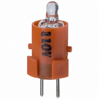
A16-1NRN
Description
NEON LAMP 110V RED FOR A16
Manufacturer
Omron
Type
Neon Lamp, 110 VoltsACr
Series
A16r
Datasheets
1.M2DA-7001.pdf
(265 pages)
2.A16-1NRN.pdf
(30 pages)
3.A16-2.pdf
(27 pages)
4.A165-CAA.pdf
(17 pages)
Specifications of A16-1NRN
Accessory Type
Neon Lamp Replacement
Supply Voltage
110V
Base Type
Bi-Pin
Colour
Red
Current Rating
1.5mA
Svhc
No SVHC (15-Dec-2010)
Illumination Colour
Red
Operating Lifetime
10000h
Voltage Rating Vac
110V
Average Bulb Life
1000
Color
Red
Illumination
Illuminated
Height
13 mm
Illumination Color
Red
Mounting Style
Snap In
Termination Style
Tabs
Lamp Base Type
Bi-Pin
Rohs Compliant
Yes
Lead Free Status / RoHS Status
Lead free / RoHS Compliant
For Use With/related Products
A16 Series
For Use With
Z1397 - SWTCH KNOB RND 3POS DPDT ILL REDZ1394 - SWTCH KNOB RND 2POS SPDT ILL REDZ1391 - SWTCH KNOB RND 2POS SPDT ILL REDZ1385 - SWITCH KNB RECT 3POS DPDT ILLZ1382 - SWITCH KNB RECT 2POS SPDT ILLZ1379 - SWITCH KNB RECT 2POS SPDT ILLZ1373 - SWITCH KNOB SQ 3-POS DPDT ILLZ1370 - SWITCH KNOB SQ 2-POS SPDT ILLZ1367 - SWITCH KNOB SQ 2-POS SPDT ILLZ1309 - SWITCH PB RND MOM DPDT ILLUM REDZ1305 - SWITCH PB RECT MOM DPDT ILLUMZ1301 - SWITCH PB SQ MOM DPDT ILLUM RED
Lead Free Status / Rohs Status
Lead free / RoHS Compliant
Other names
A161NRN
Z1342
Z1342


A3C
Installation
Mounting and Replacing the Pushbutton
Mounting Direction for the Pushbutton/Display and Lamp
Lighted Pushbutton Switch
Indicator
Note: 1. Push the projections on the Lamp into the grooves on
Mounting Direction for the Pushbutton/Display and Switch
Insert the Pushbutton/Display into the Switch so that the lamp guide
is aligned with the non-projecting part of the Switch.
Apply a pressure between 9.8 and 24.5 N.
Note: 1. The mounting direction for Indicators is 180° to that for
44
•
•
Insert the Lamp (incandescent lamp or LED lamp) into the
Pushbutton so that the lamp guide fits into the wider gap
between the projections on the Pushbutton.
With Indicators, the Lamp is inserted facing the opposite
direction (i.e., at 180°) to that for Lighted Pushbutton
Switches.
2. The Lamp for Lighted Pushbutton Switches moves, but
the Pushbutton/Display.
the Lamp for Indicators is fixed.
Lighted Pushbutton Switches. Be sure to insert the Leg-
end Plate and other parts with the correct orientation.
Groove of the Display
Projection of the Switch
Removing the Pushbutton/Display
Hold the recessed portions on the cap of the Pushbutton and pull.
Note: Do not use tools such as pliers to remove the Pushbutton as
Panel Mounting
Insert the Switch from the front of the panel. Mount the mounting nut
from the terminal end of the Switch and tighten it.
There are projections on the terminal end of the Switch which may,
depending on the orientation, block the nut. In this case, turn the nut
until it is possible to mount it. Tighten the nut to a torque between
0.20 and 0.39 N⋅m.
If soldering is used, mount the mounting nut first. Lead wires and
mounds of solder may make it impossible to mount the nut after sol-
dering.
Socket Mounting
After securing the Switch to the panel using the mounting nut, insert
the Socket into the Switch.
Align the positioning holes of the Socket with the projections of the
Switch before inserting the Socket.
2. If the terminals of the Lamp become bent, it may be
3. Take particular care about the mounting direction with
this may damage the cap.
impossible to fit them into the lamp terminal holes.
Ensure that the terminals are straight when they are
inserted.
the round models (A3CT).
Recess
Panel
Panel
Positioning hole of the
Socket
Projection of the Switch
Mounting nut
A3C
Related parts for A16-1NRN
Image
Part Number
Description
Manufacturer
Datasheet
Request
R

Part Number:
Description:
SWITCH PB SQUARE MOM SPDT GREEN
Manufacturer:
Omron
Datasheet:

Part Number:
Description:
SWITCH PB SQUARE MOM SPDT WHITE
Manufacturer:
Omron
Datasheet:
Part Number:
Description:
SWITCH PB SQUARE MOM SPDT YELLOW
Manufacturer:
Omron
Datasheet:
Part Number:
Description:
SWITCH PB RECTANG MOM SPDT BLUE
Manufacturer:
Omron
Datasheet:
Part Number:
Description:
SWITCH PB RECTANG MOM SPDT YEL
Manufacturer:
Omron
Datasheet:
Part Number:
Description:
SWITCH PB SQUARE MOM SPDT BLUE
Manufacturer:
Omron
Datasheet:
Part Number:
Description:
SWITCH PB SQUARE MOM SPDT RED
Manufacturer:
Omron
Datasheet:
Part Number:
Description:
SWITCH PB RECTANG MOM SPDT GREEN
Manufacturer:
Omron
Datasheet:
Part Number:
Description:
SWITCH PB RECTANG MOM SPDT RED
Manufacturer:
Omron
Datasheet:

Part Number:
Description:
SWITCH PB RECTANG MOM SPDT WHITE
Manufacturer:
Omron
Datasheet:
Part Number:
Description:
SWITCH PB ROUND MOM SPDT BLUE
Manufacturer:
Omron
Datasheet:
Part Number:
Description:
SWITCH PB ROUND MOM SPDT GREEN
Manufacturer:
Omron
Datasheet:
Part Number:
Description:
SWITCH PB ROUND MOM SPDT RED
Manufacturer:
Omron
Datasheet:
Part Number:
Description:
SWITCH PB ROUND MOM SPDT WHITE
Manufacturer:
Omron
Datasheet:
Part Number:
Description:
SWITCH PB ROUND MOM SPDT YELLOW
Manufacturer:
Omron
Datasheet: