D2SW-3H Omron, D2SW-3H Datasheet

SUBMINIATURE BASIC SWITCH

D2SW-3H

Manufacturer Part Number
D2SW-3H
Description
SUBMINIATURE BASIC SWITCH
Manufacturer
Omron
Series
D2SWr
Datasheets

Specifications of D2SW-3H

Operating Force
180gf
Circuit
SPDT
Switch Function
On-Mom
Contact Rating @ Voltage
3A @ 125VAC
Actuator Type
Round (Pin Plunger)
Mounting Type
Chassis Mount
Termination Style
Solder Lug
Contact Form
SPDT
Contact Rating
3 Amps
Actuator
Plunger, Pin
Contact Configuration
SPDT
Microswitch Type
Snap Action
Actuation Type
Plunger
Contact Voltage Ac Nom
250V
Contact Voltage Dc Nom
30V
Contact Current Max
3A
Switch
RoHS Compliant
Actuator Style
Plunger
Operating Force Max
1.77N
Rohs Compliant
Yes
Lead Free Status / RoHS Status
Lead free / RoHS Compliant
Lead Free Status / RoHS Status
Lead free / RoHS Compliant
Other names
D2SW3H

Available stocks

Company
Part Number
Manufacturer
Quantity
Price
Part Number:
D2SW-3H
Manufacturer:
OMRON
Quantity:
15 000
Part Number:
D2SW-3H
Manufacturer:
OMRON
Quantity:
196
A High-quality Watertight Miniature
Basic Switch Conforms to IP67
Ordering Information
Note: 1. The standard lengths of the lead wires (AV0.5f) of models incorporating them are 30 cm.
Pin plunger
Hinge lever
Simulated hinge lever
S
Hinge roller lever
Monoblock construction assures high sealing
capability and is ideal for dusty places or where
water is sprayed.
A wide operating temperature range of –40 C to
85 C is ideal for any operating environment.
Ideal for the automobile, agricultural machinery,
automatic vending machine, refrigerator, ice-
manufacturing, bath equipment, hot-water supply,
air conditioner, and factory machine industries,
which require highly environment-resistive capabil-
ities.
ge e e
ge o e e e
p u ge
u a ed
Watertight Miniature Basic Switch
2. EN61058-1 (IEC1058-1) approved by VDE.
3. UL/CSA approved lead-wired models use UL/CSA approved lead wire. Model name changes from D2SW-jM to D2SW-jMS.
ge e e
Actuator
Solder terminals
Tab terminals (#110)
PCB terminals
With lead wires
Solder terminals
Tab terminals (#110)
PCB terminals
With lead wires
Solder terminals
Tab terminals (#110)
PCB terminals
With lead wires
Solder terminals
Tab terminals (#110)
PCB terminals
With lead wires
D2SW-3H
D2SW-3T
D2SW-3D
D2SW-3M (see note 3)
D2SW-3L1H
D2SW-3L1T
D2SW-3L1D
D2SW-3L1M (see note 3)
D2SW-3L3H
D2SW-3L3T
D2SW-3L3D
D2SW-3L3M (see note 3)
D2SW-3L2H
D2SW-3L2T
D2SW-3L2D
D2SW-3L2M (see note 3)
3 A
Model
D2SW-01H (see note 2)
D2SW-01T
D2SW-01D
D2SW-01M (see note 3)
D2SW-01L1H (see note 2)
D2SW-01L1T
D2SW-01L1D
D2SW-01L1M (see note 3)
D2SW-01L3H (see note 2)
D2SW-01L3T
D2SW-01L3D
D2SW-01L3M (see note 3)
D2SW-01L2H (see note 2)
D2SW-01L2T
D2SW-01L2D
D2SW-01L2M (see note 3)
D2SW
RC
0.1A
Back
D E
V
127

Related parts for D2SW-3H

D2SW-3H Summary of contents

Page 1

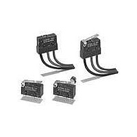
... Note: 1. The standard lengths of the lead wires (AV0.5f) of models incorporating them are 30 cm. 2. EN61058-1 (IEC1058-1) approved by VDE. 3. UL/CSA approved lead-wired models use UL/CSA approved lead wire. Model name changes from D2SW-jM to D2SW-jMS. Solder terminals D2SW-3H Tab terminals (#110) D2SW-3T PCB terminals ...

Page 2

... Non-inductive load Lamp load 0 0.5 A 0 --- --- --- --- VDE (Licence No. 85002)/EN61058-1 (IEC1058-1) Approved D2SW-01jH: D2SW-3 Rivet Silver D2SW Inductive laod Inductive load Motor load 0 0.5 A 0.3 A 0 --- --- 0 125 VAC D2SW-01 Crossbar ...

Page 3

... D2SW D2SW- max. (initial value) for lead wire models 600 VAC, 50/60 Hz for 1 min between contacts of the same polarity 1,500 VAC, 50/60 Hz for 1 min between current-carrying metal parts and ground, and between each terminal and non-current-carrying ...

Page 4

... Note: The following illustrations and dimensions are for models with soldered terminals. Refer to Terminals for models with tab (#110) and PCB terminals. The dimensions not described are the same as those of models with pin plungers. Pin Plunger D2SW-3j D2SW-01j Hinge Lever D2SW-3L1j D2SW-01L1j Simulated Hinge Lever D2SW-3L3j D2SW-01L3j Hinge Roller Lever D2SW-3L2j D2SW-01L2j 130 7.5 0.1 +0.1 2.35 dia. –0.05 holes 1 ...

Page 5

... PCB Mounting Three, 1.35 dia. to 1.5 holes 1.8 0.1 PCB thickness t = 1.6 mm 3.9 +0.15 8.8 –0.05 16.1 0.1 2.9 6.4 0.2 2.9 Three, 1.2 dia. holes Three, 0.5 2.8 6.4 0.2 D2SW 131 ...

Page 6

... Mounting Holes Two 2.4 dia. or M2.3 mounting holes 9.5 When soldering a lead wire to a terminal of the D2SW, use a solder- ing iron with a maximum capacity and do not take more than solder the lead wire, otherwise the characteristics of the D2SW may be altered. ...

Related keywords