D2SW-3H Omron, D2SW-3H Datasheet - Page 6
D2SW-3H
Manufacturer Part Number
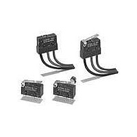
D2SW-3H
Description
SUBMINIATURE BASIC SWITCH
Manufacturer
Omron
Series
D2SWr
Specifications of D2SW-3H
Operating Force
180gf
Circuit
SPDT
Switch Function
On-Mom
Contact Rating @ Voltage
3A @ 125VAC
Actuator Type
Round (Pin Plunger)
Mounting Type
Chassis Mount
Termination Style
Solder Lug
Contact Form
SPDT
Contact Rating
3 Amps
Actuator
Plunger, Pin
Contact Configuration
SPDT
Microswitch Type
Snap Action
Actuation Type
Plunger
Contact Voltage Ac Nom
250V
Contact Voltage Dc Nom
30V
Contact Current Max
3A
Switch
RoHS Compliant
Actuator Style
Plunger
Operating Force Max
1.77N
Rohs Compliant
Yes
Lead Free Status / RoHS Status
Lead free / RoHS Compliant
Lead Free Status / RoHS Status
Lead free / RoHS Compliant
Other names
D2SW3H
Available stocks
Company
Part Number
Manufacturer
Quantity
Price
Company:

Part Number:
D2SW-3H
Manufacturer:
OMRON
Quantity:
15 000
Company:
Part Number:
D2SW-3H
Manufacturer:
OMRON
Quantity:
196


D2SW
Precautions
Mounting
Use two M3 mounting screws with spring washers to mount the
switch. Tighten the screws to a torque of 0.23 to 0.26 N m (2.3 to
2.7 kgf cm).
When soldering a lead wire to a terminal of the D2SW, use a solder-
ing iron with a maximum capacity of 60 W and do not take more than
5 s to solder the lead wire, otherwise the characteristics of the
D2SW may be altered.
Make sure that there is no icing when using the D2SW at low ambi-
ent temperatures.
Operations
Make sure that the switching object is perfectly separated from the
actuator when the switch is not operated and the actuator is pressed
appropriately by the switching object when the switch is operated.
The switch should be set so that its stroke will be within the rated OT
when the switch is operated.
Install the switching object so that its moving direction is the same
as that of the actuator.
Handle D2SW models with pin plungers with care so that the sealing
rubber parts around the pin plungers will not be damaged.
Recommended conductor size for the 0.1 A-series solder terminal
is AWG26 to 18 (0.13 to 0.83 mm
132
Cat. No. C97-E1-1
ALL DIMENSIONS SHOWN ARE IN MILLIMETERS.
To convert millimeters into inches, multiply by 0.03937. To convert grams into ounces, multiply by 0.03527.
Two 2.4 dia. or M2.3 mounting holes
Mounting Holes
9.5
2
).
Enclosure Ratings
The D2SW was tested underwater and passed the following water-
tightness tests, which however, does not mean that the D2SW can
be used in the water.
JIS C0920 (rules for testing the watertightness of electrical devices
and materials), class 7 (watertightness test). Refer to the following
illustration for the test method.
IEC Publication 529, class IP67. Refer to the following illustration for
the test method.
Note: The object to be tested is left in the water for 30 minutes
on condition that the distance between the surface of the
water and the top of the object be 15 cm minimum and
the distance between the surface of the water and the
bottom of the object be 1 m minimum.
É É É É
É É É É
É É É É
É É É É
Left for 30 mins.
Tested object
Water
15cm min.
1m min.
D2SW
Related parts for D2SW-3H
Image
Part Number
Description
Manufacturer
Datasheet
Request
R

Part Number:
Description:
SWITCH 3A BASIC SEALED SLDR TERM
Manufacturer:
Omron
Datasheet:

Part Number:
Description:
SWITCH 3A LEVER SEALED SLD TERM
Manufacturer:
Omron
Datasheet:

Part Number:
Description:
SWITCH 3A LEVER SEALED SLD TERM
Manufacturer:
Omron
Datasheet:

Part Number:
Description:
SWITCH 3A ROLLER SEALED SLDR
Manufacturer:
Omron
Datasheet:

Part Number:
Description:
SWITCH 3A LEVER SEALED 12"WIRES
Manufacturer:
Omron
Datasheet:

Part Number:
Description:
SWITCH 3A LEVER SEALED 12"WIRES
Manufacturer:
Omron
Datasheet:

Part Number:
Description:
SWITCH 3A ROLLER SEALED 12"WIRES
Manufacturer:
Omron
Datasheet:

Part Number:
Description:
SWITCH MINI SPDT .1A 60GF
Manufacturer:
Omron
Datasheet:

Part Number:
Description:
SWITCH 3A BASIC SEALED .110QC
Manufacturer:
Omron
Datasheet:

Part Number:
Description:
SWITCH 3A BASIC SEALED PC MNT
Manufacturer:
Omron
Datasheet:

Part Number:
Description:
SWITCH 3A LEVER SEALED .110QC
Manufacturer:
Omron
Datasheet:

Part Number:
Description:
SWITCH 3A BASIC SEALED 12"WIRES
Manufacturer:
Omron
Datasheet:
Part Number:
Description:
MINIATURE BASIC SWITCH
Manufacturer:
Omron
Datasheet:
Part Number:
Description:
SWITCH MINI SPDT .1A 60GF
Manufacturer:
Omron
Datasheet:

Part Number:
Description:
SWITCH BASIC SPDT 2A .110QC
Manufacturer:
Omron
Datasheet: