PIC18F24K22-I/SO Microchip Technology, PIC18F24K22-I/SO Datasheet - Page 164
PIC18F24K22-I/SO
Manufacturer Part Number
PIC18F24K22-I/SO
Description
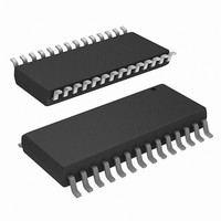
IC PIC MCU 16KB FLASH 28SOIC
Manufacturer
Microchip Technology
Series
PIC® XLP™ 18Fr
Datasheets
1.PIC16F722-ISS.pdf
(8 pages)
2.PIC18F26J13-ISS.pdf
(496 pages)
3.PIC18F24K22-ISP.pdf
(494 pages)
Specifications of PIC18F24K22-I/SO
Core Size
8-Bit
Program Memory Size
16KB (8K x 16)
Core Processor
PIC
Speed
64MHz
Connectivity
I²C, SPI, UART/USART
Peripherals
Brown-out Detect/Reset, HLVD, POR, PWM, WDT
Number Of I /o
24
Program Memory Type
FLASH
Eeprom Size
256 x 8
Ram Size
768 x 8
Voltage - Supply (vcc/vdd)
1.8 V ~ 5.5 V
Data Converters
A/D 19x10b
Oscillator Type
Internal
Operating Temperature
-40°C ~ 85°C
Package / Case
28-SOIC (0.300", 7.50mm Width)
Controller Family/series
PIC18
No. Of I/o's
25
Eeprom Memory Size
256Byte
Ram Memory Size
768Byte
Cpu Speed
64MHz
No. Of Timers
7
Lead Free Status / RoHS Status
Lead free / RoHS Compliant
Available stocks
Company
Part Number
Manufacturer
Quantity
Price
Company:

Part Number:
PIC18F24K22-I/SO
Manufacturer:
MICRON
Quantity:
12


PIC18(L)F2X/4XK22
FIGURE 12-2:
12.7
Timer1/3/5 can be configured to count freely or the
count can be enabled and disabled using Timer1/3/5
Gate circuitry. This is also referred to as Timer1/3/5
Gate Enable.
Timer1/3/5 Gate can also be driven by multiple
selectable sources.
12.7.1
The Timer1/3/5 Gate Enable mode is enabled by
setting the TMRxGE bit of the TxGCON register. The
polarity of the Timer1/3/5 Gate Enable mode is
configured using the TxGPOL bit of the TxGCON
register.
When Timer1/3/5 Gate Enable mode is enabled,
Timer1/3/5 will increment on the rising edge of the
Timer1/3/5 clock source. When Timer1/3/5 Gate
Enable mode is disabled, no incrementing will occur
and Timer1/3/5 will hold the current count. See
Figure 12-4
TABLE 12-3:
DS41412D-page 164
TxCLK
Timer1/3/5 Gate
TMR1L
TxGPOL
TIMER1/3/5 GATE ENABLE
for timing details.
0
0
1
1
8
TIMER1/3/5 GATE ENABLE
SELECTIONS
8
TIMER1/3/5 16-BIT
READ/WRITE MODE
BLOCK DIAGRAM
High Byte
TMR1H
TMR1
8
TxG
0
1
0
1
8
8
Counts
Holds Count
Holds Count
Counts
Internal Data Bus
Read TMR1L
Write TMR1L
Timer1/3/5
Operation
on Overflow
Timer1/3/5
Circuitry
TMR1IF
From
Set
Preliminary
12.7.2
The Timer1/3/5 Gate source can be selected from one
of four different sources. Source selection is controlled
by the TxGSS bits of the TxGCON register. The polarity
for each available source is also selectable. Polarity
selection is controlled by the TxGPOL bit of the
TxGCON register.
TABLE 12-4:
The Gate resource, Timer2 Match to PR2, changes
between Timer2, Timer4 and Timer6 depending on
which of the three 16-bit Timers, Timer1, Timer3 or
Timer5, is selected. See
Timer2/4/6 Match to PR2/4/6 combination is available
for the 16-bit timer being used.
TABLE 12-5:
12.7.2.1
The TxG pin is one source for Timer1/3/5 Gate Control.
It can be used to supply an external source to the
Timer1/3/5 Gate circuitry.
12.7.2.2
The TMR2/4/6 register will increment until it matches
the value in the PR2/4/6 register. On the very next
increment cycle, TMR2/4/6 will be reset to 00h. When
this Reset occurs, a low-to-high pulse will automatically
be generated and internally supplied to the Timer1/3/5
Gate circuitry. See
Source Selection”
Timer1
Timer3
Timer5
TxGSS
Timer1/3/5 Resource
00
01
10
11
Timer1/3/5 Gate Pin
Timer2/4/6 Match to PR2/4/6
(TMR2/4/6 increments to match PR2/4/6)
Comparator 1 Output SYNCC1OUT
(optionally Timer1/3/5 synchronized out-
put)
Comparator 2 Output SYNCC2OUT
(optionally Timer1/3/5 synchronized out-
put)
TIMER1/3/5 GATE SOURCE
SELECTION
TxG Pin Gate Operation
Timer2/4/6 Match Gate Operation
TIMER1/3/5 GATE SOURCES
GATE RESOURCES FOR
TIMER2/4/6 MATCH TO
PR2/4/6
Timer1/3/5 Gate Source
Section 12.7.2 “Timer1/3/5 Gate
for more information.
2010 Microchip Technology Inc.
Table 12-5
TMR2 Match to PR2
TMR4 Match to PR4
TMR6 Match to PR6
Timer1/3/5 Gate Match
Selection
to determine which
Related parts for PIC18F24K22-I/SO
Image
Part Number
Description
Manufacturer
Datasheet
Request
R

Part Number:
Description:
Manufacturer:
Microchip Technology Inc.
Datasheet:
Part Number:
Description:
Manufacturer:
Microchip Technology Inc.
Datasheet:
Part Number:
Description:
Manufacturer:
Microchip Technology Inc.
Datasheet:
Part Number:
Description:
Manufacturer:
Microchip Technology Inc.
Datasheet:
Part Number:
Description:
Manufacturer:
Microchip Technology Inc.
Datasheet:
Part Number:
Description:
Manufacturer:
Microchip Technology Inc.
Datasheet:
Part Number:
Description:
Manufacturer:
Microchip Technology Inc.
Datasheet:
Part Number:
Description:
Manufacturer:
Microchip Technology Inc.
Datasheet: