PIC18F24K22-I/SO Microchip Technology, PIC18F24K22-I/SO Datasheet - Page 63
PIC18F24K22-I/SO
Manufacturer Part Number
PIC18F24K22-I/SO
Description
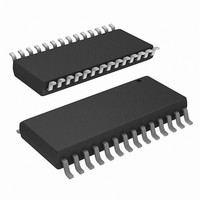
IC PIC MCU 16KB FLASH 28SOIC
Manufacturer
Microchip Technology
Series
PIC® XLP™ 18Fr
Datasheets
1.PIC16F722-ISS.pdf
(8 pages)
2.PIC18F26J13-ISS.pdf
(496 pages)
3.PIC18F24K22-ISP.pdf
(494 pages)
Specifications of PIC18F24K22-I/SO
Core Size
8-Bit
Program Memory Size
16KB (8K x 16)
Core Processor
PIC
Speed
64MHz
Connectivity
I²C, SPI, UART/USART
Peripherals
Brown-out Detect/Reset, HLVD, POR, PWM, WDT
Number Of I /o
24
Program Memory Type
FLASH
Eeprom Size
256 x 8
Ram Size
768 x 8
Voltage - Supply (vcc/vdd)
1.8 V ~ 5.5 V
Data Converters
A/D 19x10b
Oscillator Type
Internal
Operating Temperature
-40°C ~ 85°C
Package / Case
28-SOIC (0.300", 7.50mm Width)
Controller Family/series
PIC18
No. Of I/o's
25
Eeprom Memory Size
256Byte
Ram Memory Size
768Byte
Cpu Speed
64MHz
No. Of Timers
7
Lead Free Status / RoHS Status
Lead free / RoHS Compliant
Available stocks
Company
Part Number
Manufacturer
Quantity
Price
Company:

Part Number:
PIC18F24K22-I/SO
Manufacturer:
MICRON
Quantity:
12


TABLE 4-1:
4.5
PIC18(L)F2X/4XK22
separate on-chip timers that help regulate the Power-
on Reset process. Their main function is to ensure that
the device clock is stable before code is executed.
These timers are:
• Power-up Timer (PWRT)
• Oscillator Start-up Timer (OST)
• PLL Lock Time-out
4.5.1
The Power-up Timer (PWRT) of PIC18(L)F2X/
4XK22 devices is an 11-bit counter which uses the
LFINTOSC source as the clock input. This yields an
approximate time interval of 2048 x 32 s = 65.6 ms.
While the PWRT is counting, the device is held in
Reset.
The power-up time delay depends on the LFINTOSC
clock and will vary from chip-to-chip due to temperature
and process variation.
The PWRT is enabled by clearing the PWRTEN
Configuration bit.
4.5.2
The Oscillator Start-up Timer (OST) provides a 1024
oscillator cycle (from OSC1 input) delay after the
PWRT delay is over. This ensures that the crystal
oscillator or resonator has started and stabilized.
The OST time-out is invoked only for XT, LP and HS
modes and only on Power-on Reset, or on exit from all
power-managed modes that stop the external oscillator.
2010 Microchip Technology Inc.
BOREN1
BOR Configuration
0
0
1
1
Device Reset Timers
POWER-UP TIMER (PWRT)
OSCILLATOR START-UP TIMER
(OST)
BOREN0
0
1
0
1
BOR CONFIGURATIONS
devices
(RCON<6>)
Unavailable
Unavailable
Unavailable
SBOREN
Available
Status of
incorporate
BOR disabled; must be enabled by reprogramming the Configuration bits.
BOR enabled by software; operation controlled by SBOREN.
BOR enabled by hardware in Run and Idle modes, disabled during
Sleep mode.
BOR enabled by hardware; must be disabled by reprogramming the Configuration bits.
three
Preliminary
4.5.3
With the PLL enabled, the time-out sequence following a
Power-on Reset is slightly different from other oscillator
modes. A separate timer is used to provide a fixed time-
out that is sufficient for the PLL to lock to the main
oscillator frequency. This PLL lock time-out (T
typically 2 ms and follows the oscillator start-up time-out.
4.5.4
On power-up, the time-out sequence is as follows:
1.
2.
The total time-out will vary based on oscillator
configuration and the status of the PWRT.
Figure
depict time-out sequences on power-up, with the
Power-up Timer enabled and the device operating in
HS Oscillator mode. Figures
apply to devices operating in XT or LP modes. For
devices in RC mode and with the PWRT disabled, on
the other hand, there will be no time-out at all.
Since the time-outs occur from the POR pulse, if MCLR
is kept low long enough, all time-outs will expire, after
which, bringing MCLR high will allow program
execution to begin immediately
useful for testing purposes or to synchronize more than
one PIC
PIC18(L)F2X/4XK22
After the POR pulse has cleared, PWRT time-out
is invoked (if enabled).
Then, the OST is activated.
BOR Operation
4-4,
®
MCU device operating in parallel.
PLL LOCK TIME-OUT
TIME-OUT SEQUENCE
Figure
4-5,
Figure 4-6
4-3
(Figure
and
DS41412D-page 63
through
Figure 4-7
4-5). This is
Figure
4-6
PLL
also
4-3,
) is
all
Related parts for PIC18F24K22-I/SO
Image
Part Number
Description
Manufacturer
Datasheet
Request
R

Part Number:
Description:
Manufacturer:
Microchip Technology Inc.
Datasheet:
Part Number:
Description:
Manufacturer:
Microchip Technology Inc.
Datasheet:
Part Number:
Description:
Manufacturer:
Microchip Technology Inc.
Datasheet:
Part Number:
Description:
Manufacturer:
Microchip Technology Inc.
Datasheet:
Part Number:
Description:
Manufacturer:
Microchip Technology Inc.
Datasheet:
Part Number:
Description:
Manufacturer:
Microchip Technology Inc.
Datasheet:
Part Number:
Description:
Manufacturer:
Microchip Technology Inc.
Datasheet:
Part Number:
Description:
Manufacturer:
Microchip Technology Inc.
Datasheet: