EE-SY672 Omron, EE-SY672 Datasheet - Page 4
EE-SY672
Manufacturer Part Number
EE-SY672
Description
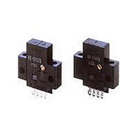
Photomicrosensors REFL LIGHT-ON/DRK-ON
Manufacturer
Omron
Series
-r
Specifications of EE-SY672
Output Configuration
Light-On/Dark-On
Sensing Distance
1 mm to 5 mm
Sensing Method
Reflective
No. Of Pins
4
Opto Case Style
Module
No. Of Channels
1
Operating Temperature Range
-10°C To +55°C
Operating Voltage Max
24VDC
Operating Voltage Min
5VDC
Input Current Max
40mA
Svhc
No SVHC (15-Dec-2010)
Frequency Response Max
50Hz
Sensing Range Max
5mm
Sensor Input
Optical
Supply Voltage Dc Max
24V
Connector Type
DEDICATED 1 OR 2
External Depth
7mm
Output Type
Light - Off / On
External Length / Height
25mm
External Width
25.4mm
Fixing Centres
19mm
Sensing Object
White Paper
Sensing Light
Infrared
Mounting Type
Solder
Current - Supply
40mA
Voltage - Supply
5 V ~ 24 V
Package / Case
Module, Connector
Features
Supports Connection With PLCs
Input Current
40mA
Rohs Compliant
Yes
Lead Free Status / RoHS Status
Lead free / RoHS Compliant
Lead Free Status / RoHS Status
Lead free / RoHS Compliant
Available stocks
Company
Part Number
Manufacturer
Quantity
Price
Company:

Part Number:
EE-SY672
Manufacturer:
Omron Electronics
Quantity:
135
Company:
Part Number:
EE-SY672
Manufacturer:
XG
Quantity:
18 970


Precautions
Refer to General Precautions on page 23 to 28 for general precautions.
Do not use this product in sensing devices
designed to provide human safety.
Make sure that this product is used within the rated
ambient environment conditions.
● Wiring
Soldering
Soldering Conditions
Cable Extension
● Installation
The photomicrosensor is built into the device being used and
so is not equipped to deal with interference from an external
light source. When using the sensor in an area exposed to an
incandescent lamp, install so as to minimize the effects of
external light sources.
76
• When direct soldering to the terminal, use the following
Solder-
• The terminal base uses a polycarbonate resin, which could
• When extending the cable, use an extension cable with
• To use a cable length longer than 10 m, attach a capacitor
guidelines.
be deformed by excessive soldering heat, resulting in
damage to the product’s functionality.
conductors having a total cross-section area of 0.3 mm
The total cable length must be 10 m maximum.
with a capacitance of approximately 10 µF to the wires as
shown below. The distance between the terminal and the
capacitor must be within 10 m. (Use a capacitor with a
dielectric strength that is at least twice the Sensor's power
supply voltage.)
Item
iron
ing
Temper-
350°C
ature
max.
Precautions for Correct Use
EE-SY671/672
OUT
Permissible
max.
time
3 s
10 m max.
Warning
A capacitor of
10 µF min.
5 to 24 VDC
The portion between the
base of the terminals and the
position 1.5 mm from the ter-
minal base must not be sol-
dered.
0V
Reflective Photomicrosensor with Sensitivity Adjuster (Non-modulated)
−
+
Remarks
Extending cable
2
.
● Sensitivity Adjustment
Use the special screwdriver (sold together) for sensitivity
adjustment.
• The sensitivity adjuster can be turned clockwise and
• The shaft of the sensitivity adjuster is charged. Connect a
Power
source
Power
source
counterclockwise endlessly. This means when the
sensitivity of the photomicrosensor is at the maximum,
turning the adjuster further clockwise will abruptly drop the
sensitivity to the minimum. For this reason, use due caution
when using the photomicrosensor at its maximum
sensitivity.
DC power supply incorporating an insulated transformer to
the photomicrosensor. Do not connect a DC power supply
incorporating an autotransformer or the user may receive
an electric shock when adjusting the sensitivity.
Insulated transformer
Autotransformer
+
−
+
−
Sensor
Sensor
Related parts for EE-SY672
Image
Part Number
Description
Manufacturer
Datasheet
Request
R

Part Number:
Description:
Photomicrosensors 13mm P Modulated SLOT PMS L-On
Manufacturer:
Omron
Datasheet:

Part Number:
Description:
Photomicrosensors PMOD 5mmSD D-ON SS
Manufacturer:
Omron
Datasheet:
Part Number:
Description:
Photomicrosensors DIFFUSE PMS PMOD 5mm
Manufacturer:
Omron
Datasheet:

Part Number:
Description:
Photomicrosensors CONV REFL DARK-ON
Manufacturer:
Omron
Datasheet:
Part Number:
Description:
Photomicrosensors 5MM LIGHT-ON REFLECT
Manufacturer:
Omron
Datasheet:

Part Number:
Description:
Photomicrosensors REFL PHOTO IC
Manufacturer:
Omron
Datasheet:
Part Number:
Description:
Photomicrosensors CONV REFL LIGHT-ON
Manufacturer:
Omron
Datasheet:

Part Number:
Description:
Photomicrosensors REFL LIGHT-ON/DRK-ON
Manufacturer:
Omron
Datasheet:
Part Number:
Description:
Photomicrosensors CONV REFL LIGHT-ON
Manufacturer:
Omron
Datasheet:

Part Number:
Description:
Photomicrosensors REFL LIGHT-ON
Manufacturer:
Omron
Datasheet:


Part Number:
Description:
PHOTO MICROSENSOR
Manufacturer:
Omron
Datasheet:

Part Number:
Description:
PHOTO MICROSENSOR :
Manufacturer:
Omron
Datasheet:

Part Number:
Description:
PHOTO MICROSENSOR
Manufacturer:
Omron
Datasheet:

Part Number:
Description:
PHOTO MICROSENSOR
Manufacturer:
Omron
Datasheet: