RDK-242 Power Integrations, RDK-242 Datasheet - Page 11
RDK-242
Manufacturer Part Number
RDK-242
Description
Power Management Modules & Development Tools TOPSwitch-JX REF. DESIGN KIT
Manufacturer
Power Integrations
Type
MOSFET & Power Driverr
Datasheet
1.RDK-242.pdf
(59 pages)
Specifications of RDK-242
Input Voltage
85 VAC to 264 VAC
Output Voltage
12 V
Maximum Operating Temperature
+ 40 C
Minimum Operating Temperature
0 C
Operating Supply Voltage
85 VAC to 264 VAC
Product
Power Management Modules


01-Mar-10
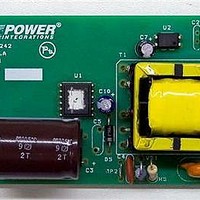
RDR-242 – 30 W Open Frame Supply using TOP266VG
4.2 Function Block Descriptions
4.2.1 Input EMI Filtering
Common-mode inductors L1 and X capacitor C1 provides CM and DM noise filtering. The
frequency jittering feature of the TOPSwitch-JX allows a very small X capacitor (100 nF)
to be used in meeting Class B Emission limits. This also eliminates the need for
discharge resistors required for meeting safety standards.
Y capacitor C11, connected between the primary and secondary side in conjunction with
T1 shield and cancellation windings provides common mode filtering.
4.2.2 TOPSwitch-JX Primary
The EcoSmart feature of U1 automatically provides constant efficiency over the entire
load range. It uses a proprietary Multi-Cycle-Modulation (MCM) function to eliminate the
need for special operating modes triggered at specific loads. This simplifies circuit design
since it removes the need to design for aberrant or specific operating conditions or load
thresholds.
Capacitor C10 provides the auto-restart timing for U1. At startup this capacitor is charged
through the DRAIN (D) pin. Once it is charged U1 begins to switch. Capacitor C10 stores
enough energy to ensure the power supply starts up. After start-up the bias winding
powers the controller via the CONTROL pin. Bypass capacitor C9 is placed as physically
close as possible to U1. Resistor R16 provides additional compensation to the feedback
loop.
4.2.3 Thermal Overload Protection
IC U1 has an integrated accurate hysteretic thermal overload protection function. When
the junction temperature of U1 reaches +142 °C (typical temperature shutdown
threshold) during a fault condition, the IC shuts down. It automatically recovers once the
junction temperature has decreased by 75 °C.
4.2.4 Output Overvoltage Protection
Open-loop faults cause the output voltage to exceed the specified maximum value. To
prevent excessive output voltage levels in such cases, U1 utilizes an output overvoltage
shutdown function. An increase in output voltage causes an increase in the bias winding
on the primary side, sensed by VR3. A sufficient rise in the bias voltage causes VR3 to
conduct and inject current into the VOLTAGE (V) pin of U1. When the current exceeds
336 A for more than 100 s, U1 enters the latching overvoltage shutdown mode.
4.2.5 Output Power Limiting with Line Voltage
Resistors R3, R4, and R15 reduce the external current limit of U1 as the line voltage
increases. This allows the supply to limit the output power to <100 VA at high line while
still delivering the rated output at low line, and to provide a nearly constant output power
level with changing line voltages. The line sensing resistors R1 and R2, in conjunction
with R12, set the undervoltage and overvoltage thresholds for U1. R12 provides
Power Integrations
Tel: +1 408 414 9200 Fax: +1 408 414 9201
Page 11 of 59
www.powerint.com
Related parts for RDK-242
Image
Part Number
Description
Manufacturer
Datasheet
Request
R

Part Number:
Description:
KIT REF DESIGN TOP HX FOR TOP258
Manufacturer:
Power Integrations
Datasheet:

Part Number:
Description:
KIT REF DESIGN LINKSWITCH 2
Manufacturer:
Power Integrations
Datasheet:

Part Number:
Description:
KIT REF DESIGN 1.2W PS TN FAMILY
Manufacturer:
Power Integrations
Datasheet:

Part Number:
Description:
KIT REF DESIGN 36-72W MOTOR DRVR
Manufacturer:
Power Integrations
Datasheet:

Part Number:
Description:
KIT REF DESIGN FOR LNK457D
Manufacturer:
Power Integrations
Datasheet:

Part Number:
Description:
REFERENCE DESIGN LINKSWITCH-PH
Manufacturer:
Power Integrations
Datasheet:

Part Number:
Description:
Specifications: Manufacturer: Power Integrations ; Output Voltage: 380 VDC ; Input / Supply Voltage (Max): 264 VAC ; Input / Supply Voltage (Min): 90 VAC ; Mounting Style: Through Hole ; Output Current: 0.913 A ; Output Power: 347 W
Manufacturer:
Power Integrations, Inc.
Part Number:
Description:
Power Management IC Development Tools REF DESIGN RDR-292 PFF LED STREET LIGHT
Manufacturer:
Power Integrations

Part Number:
Description:
KIT REF DESIGN FOR LNK403EG
Manufacturer:
Power Integrations
Datasheet:

Part Number:
Description:
KIT REF DESIGN FOR LNK406EG
Manufacturer:
Power Integrations
Datasheet:

Part Number:
Description:
KIT REF DESIGN DG CAPZERO
Manufacturer:
Power Integrations
Datasheet:

Part Number:
Description:
KIT REF DESIGN LINKSWITCH-CV
Manufacturer:
Power Integrations
Datasheet:

Part Number:
Description:
KIT REF DESIGN PFS762HG
Manufacturer:
Power Integrations
Datasheet:
Part Number:
Description:
Specifications: Family: Eval Boards - DC/DC & AC/DC (Off-Line) SMPS ; Series: HiperLCS™ ; Main Purpose: DC/DC, Step Down ; Outputs and Type: 1, Isolated ; Power - Output: 150W ; Voltage - Output: 24V ; Current - Output: 6.25A ; Voltage - Input:
Manufacturer:
Power Integrations, Inc.
Datasheet:

Part Number:
Description:
KIT REFERENCE DESIGN W/TN376PN
Manufacturer:
Power Integrations
Datasheet: