RDK-242 Power Integrations, RDK-242 Datasheet - Page 20
RDK-242
Manufacturer Part Number
RDK-242
Description
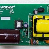
Power Management Modules & Development Tools TOPSwitch-JX REF. DESIGN KIT
Manufacturer
Power Integrations
Type
MOSFET & Power Driverr
Datasheet
1.RDK-242.pdf
(59 pages)
Specifications of RDK-242
Input Voltage
85 VAC to 264 VAC
Output Voltage
12 V
Maximum Operating Temperature
+ 40 C
Minimum Operating Temperature
0 C
Operating Supply Voltage
85 VAC to 264 VAC
Product
Power Management Modules


VUV_STARTUP
VOV_SHUTDOWN
RLS
OUTPUT OVERVOLTAGE
VZ
RZ
OVERLOAD POWER
LIMITING
Overload Current Ratio at
VMAX
Overload Current Ratio at
VMIN
ILIMIT_EXT_VMIN
ILIMIT_EXT_VMAX
RIL
RPL
ENTER TRANSFORMER CORE/CONSTRUCTION VARIABLES
Core Type
Core
Bobbin
AE
LE
AL
BW
M
L
NS
DC INPUT VOLTAGE PARAMETERS
VMIN
VMAX
CURRENT WAVEFORM SHAPE PARAMETERS
DMAX
IAVG
IP
IR
IRMS
Power Integrations, Inc.
Tel: +1 408 414 9200 Fax: +1 408 414 9201
www.powerint.com
Auto
0.00
2.00
EF25_BO
EF25
BBIN
12.88
0.518
EF25
2000
1.11
1.01
0.97
5.78
15.6
0.60
0.42
1.01
0.63
0.56
445
N/A
375
4.0
5.1
1.2
95
27
90
6
M-ohms
M-ohms
k-ohms
k-ohms
nH/T^2
Amps
Amps
Amps
Amps
cm^2
Volts
Volts
Volts
Volts
Volts
P/N:
P/N:
mm
mm
cm
A
A
Minimum DC Bus Voltage at which the
power supply will start-up
Typical DC Bus Voltage at which power
supply will shut-down (Max)
Use two standard, 2 M-Ohm, 5% resistors in
series for line sense functionality.
Zener Diode rated voltage for Output
Overvoltage shutdown protection
Output OVP resistor. For latching shutdown
use 20 ohm resistor instead
X pin functionality
Enter the desired margin to current limit at
VMAX. A value of 1.2 indicates that the
current limit should be 20% higher than peak
primary current at VMAX
Margin to current limit at low line.
Peak primary Current at VMIN
Peak Primary Current at VMAX
Current limit/Power Limiting resistor.
Resistor not required. Use RIL resistor only
Core Type
PC40EF25-Z
*
Core Effective Cross Sectional Area
Core Effective Path Length
Ungapped Core Effective Inductance
Bobbin Physical Winding Width
Safety Margin Width (Half the Primary to
Secondary Creepage Distance)
Number of Primary Layers
Number of Secondary Turns
Minimum DC Input Voltage
Maximum DC Input Voltage
Maximum Duty Cycle (calculated at
PO_PEAK)
Average Primary Current (calculated at
average output power)
Peak Primary Current (calculated at Peak
output power)
Primary Ripple Current (calculated at
average output power)
Primary RMS Current (calculated at average
output power)
Page 20 of 59
Related parts for RDK-242
Image
Part Number
Description
Manufacturer
Datasheet
Request
R

Part Number:
Description:
KIT REF DESIGN TOP HX FOR TOP258
Manufacturer:
Power Integrations
Datasheet:

Part Number:
Description:
KIT REF DESIGN LINKSWITCH 2
Manufacturer:
Power Integrations
Datasheet:

Part Number:
Description:
KIT REF DESIGN 1.2W PS TN FAMILY
Manufacturer:
Power Integrations
Datasheet:

Part Number:
Description:
KIT REF DESIGN 36-72W MOTOR DRVR
Manufacturer:
Power Integrations
Datasheet:

Part Number:
Description:
KIT REF DESIGN FOR LNK457D
Manufacturer:
Power Integrations
Datasheet:

Part Number:
Description:
REFERENCE DESIGN LINKSWITCH-PH
Manufacturer:
Power Integrations
Datasheet:

Part Number:
Description:
Specifications: Manufacturer: Power Integrations ; Output Voltage: 380 VDC ; Input / Supply Voltage (Max): 264 VAC ; Input / Supply Voltage (Min): 90 VAC ; Mounting Style: Through Hole ; Output Current: 0.913 A ; Output Power: 347 W
Manufacturer:
Power Integrations, Inc.
Part Number:
Description:
Power Management IC Development Tools REF DESIGN RDR-292 PFF LED STREET LIGHT
Manufacturer:
Power Integrations

Part Number:
Description:
KIT REF DESIGN FOR LNK403EG
Manufacturer:
Power Integrations
Datasheet:

Part Number:
Description:
KIT REF DESIGN FOR LNK406EG
Manufacturer:
Power Integrations
Datasheet:

Part Number:
Description:
KIT REF DESIGN DG CAPZERO
Manufacturer:
Power Integrations
Datasheet:

Part Number:
Description:
KIT REF DESIGN LINKSWITCH-CV
Manufacturer:
Power Integrations
Datasheet:

Part Number:
Description:
KIT REF DESIGN PFS762HG
Manufacturer:
Power Integrations
Datasheet:
Part Number:
Description:
Specifications: Family: Eval Boards - DC/DC & AC/DC (Off-Line) SMPS ; Series: HiperLCS™ ; Main Purpose: DC/DC, Step Down ; Outputs and Type: 1, Isolated ; Power - Output: 150W ; Voltage - Output: 24V ; Current - Output: 6.25A ; Voltage - Input:
Manufacturer:
Power Integrations, Inc.
Datasheet:

Part Number:
Description:
KIT REFERENCE DESIGN W/TN376PN
Manufacturer:
Power Integrations
Datasheet: