LPR2430ERA RFM, LPR2430ERA Datasheet
LPR2430ERA
Specifications of LPR2430ERA
Available stocks


Related parts for LPR2430ERA


LPR2430ERA Summary of contents
Page 1
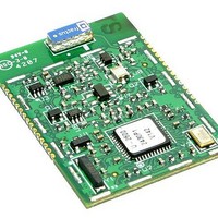
... Sleep Current less than 3 µA • FCC, Canadian IC and ETSI Certified for Unlicensed Operation The LPR2430ERA 2.4 GHz transceiver module is a low cost, high-power solution for peer-to-peer, point-to-point and point-to-multipoint wireless designs. LPR2430ERA modules provide the flexibility and versatility to serve applications ranging from cable replacements to sensor networks ...
Page 2
... E-mail: info@rfm.com ©2009 by RF Monolithics, Inc. Sym Notes Minimum Typical 1.2, 2.4, 4.8, 9.6 (default), 19.2, 28.8, 38.4, 57.6, 76.8, 115.2 -0 130 -40 Maximum Units 3.3 V bits MW 16 bits kb/s 0 +5.5 Vdc µ Page LPR2430ERA - 06/19/09 ...
Page 3
... In addition, CNL supports analog and digital I/O binding, which maps an ADC measurement and the states of two digital inputs on one LPR2430ERA to a PWM output and two digital outputs on another LPR2430ERA. See the LPR2430 Series Integration Guide for complete details of the CNL API ...
Page 4
... LPR2430ERA I/O Pad Descriptions Pin Name I/O 1 GND - Power supply and signal ground. Connect to the host circuit board ground. 2 ACTIVITY O RF activity indicator. Output pulses high when a packet is sent or received. 3 LINK O Link indicator. Output is high when the radio has successfully joined a network. ...
Page 5
... Reflow Profile An example solder reflow profile for mounting the radio module on its host circuit board is shown in Figure 3. Note: Specifications subject to change without notice. www.RFM.com E-mail: info@rfm.com ©2009 by RF Monolithics, Inc. Figure 2 Figure 3 Part # M-2430-0005, Rev A Page LPR2430ERA - 06/19/09 ...