LPR2430ERA RFM, LPR2430ERA Datasheet - Page 4
LPR2430ERA
Manufacturer Part Number
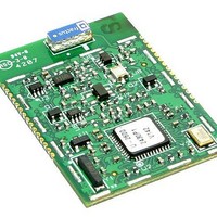
LPR2430ERA
Description
Zigbee / 802.15.4 Modules & Development Tools 100mW Analog&Digital I/O w/Chip Antenna
Manufacturer
RFM
Datasheet
1.LPR2430ERA.pdf
(5 pages)
Specifications of LPR2430ERA
Wireless Frequency
2.4 GHz
Modulation
OQPSK
Operating Voltage
3.3 V
Output Power
100 mW
Antenna
Chip
Operating Temperature Range
- 40 C to + 85 C
For Use With/related Products
CC2430
Lead Free Status / RoHS Status
Lead free / RoHS Compliant
Available stocks
Company
Part Number
Manufacturer
Quantity
Price
Company:

Part Number:
LPR2430ERA
Manufacturer:
RFM
Quantity:
12 800
Company:
Part Number:
LPR2430ERADK
Manufacturer:
RFM
Quantity:
12 800


LPR2430ERA I/O Pad Descriptions
www.RFM.com E-mail: info@rfm.com
©2009 by RF Monolithics, Inc.
Pin
10
11
12
13
14
15
16
17
18
19
20
21
22
23
24
25
26
27
28
29
30
1
2
3
4
5
6
7
8
9
(/HOST_CTS )
(/HOST_RTS)
RADIO_RXD
RADIO_TXD
(RS485_EN)
(ADC_REF)
ADC_VDD
ACTIVITY
(PWM1)
(GPIO2)
/RESET
GPIO4
GPIO0
GPIO5
PWM0
GPIO2
GPIO1
GPIO3
PWM1
Name
ADC0
ADC1
RSVD
RSVD
RSVD
RSVD
ADC2
GND
LINK
GND
GND
GND
GND
VCC
NC
NC
NC
I/O
I/O
I/O
I/O
-
I/O
I/O
I/O
O
O
O
O
O
O
-
I
I
-
-
I
I
I
-
-
-
-
I
-
-
-
-
Power supply and signal ground. Connect to the host circuit board ground.
RF activity indicator. Output pulses high when a packet is sent or received.
Link indicator. Output is high when the radio has successfully joined a network.
Configurable digital I/O port 0. When configured as an output, the power-on state is also configurable. This pin can also
be configured as a reference voltage input for the ADCs, 0 to 3.3 V, 1.25 V typical.
Serial data output (UART) from the radio to the host.
Serial data input (UART) from the host to the radio.
Configurable digital I/O port 4. When configured as an output, the power-on state is also configurable. Also configurable
as UART flow control output. The LPR2430 sets this line low to indicate it is ready to accept data from the host on the
RADIO_RXD input. When the LPR2430 sets this line high, the host must stop sending data. The default state is GPIO4.
Configurable digital I/O port 5. When configured as an output, the power-on state is also configurable. Also configurable
as UART flow control input. The host sets this line low to allow data to flow from the RADIO_TXD pin. When the host sets
this line high, the LPR2430 will stop sending data to the host. The default state is GPIO5
Pulse-width modulated output 0 with internal low-pass filter. Provides a DAC function, 0 to 3.3 V.
Configurable digital I/O port 2. When configured as an output, the power-on state is also configurable. This pin is con-
nected to the input of the low-pass filter driving Pin 13, and is also configurable as a PWM output.
Configurable digital I/O port 1. When configured as an output, the power-on state is also configurable.
Configurable digital I/O port 3. When configured as an output, this high current port can sink up to 20 mA. The power-on
output state is also configurable. Can also be configured as active low transmit enable for controlling an RS485 or other
half-duplex bus driver.
GPIO2 (Pin 10) drives this pin through a low-pass filter. Provides a DAC function when GPIO2 is configured as a PWM
output.
Power supply input, +3.3 to +5.5 Vdc.
Power supply and signal grounds. Connect to the host circuit board ground.
Power supply and signal grounds. Connect to the host circuit board ground.
Active low module hardware reset. Hold this input low when the power supply input is less than 3.3 Vdc. The module firm-
ware boots up and will accept commands about 3 seconds after this input goes high.
11-bit ADC input 0. ADC full scale reading can be referenced to the module’s +3.3 V regulated supply, the ADC’s internal
+2.5 V reference, or ADC_REF (Pin 4).
ADC input 1. Same configuration options as ADC0.
Reserved pin. Leave unconnected.
Reserved pin. Leave unconnected.
Reserved pin. Leave unconnected.
Reserved pin. Leave unconnected.
ADC input 2. Same configuration options as ADC0.
Module’s +3.3 V regulated supply, used for ratiometric ADC readings. Current drain should be less than 5 mA.
No connection.
No connection.
RF ground. Connect to the host circuit board ground plane, and to shield when using coaxial cable.
No connection.
RF ground. Connect to the host circuit board ground plane, and to shield when using coaxial cable.
Description
.
LPR2430ERA - 06/19/09
Page 4 of 5
Related parts for LPR2430ERA
Image
Part Number
Description
Manufacturer
Datasheet
Request
R

Part Number:
Description:
Zigbee / 802.15.4 Modules & Development Tools 1mW Transmit Power 250 kb/s
Manufacturer:
RFM
Datasheet:

Part Number:
Description:
ASH RX 115.2 KBPS 433.92 MHZ
Manufacturer:
RFM
Datasheet:

Part Number:
Description:
RFIC TRANCEIVER MULTI-CHANNEL FS
Manufacturer:
RFM
Datasheet:

Part Number:
Description:
ASH TX 115.2 KBPS 433.92 MHZ
Manufacturer:
RFM
Datasheet:
Part Number:
Description:
Filters 1602MHz BW=61MHz
Manufacturer:
RFM
Datasheet:

Part Number:
Description:
RESONATOR, SM3030-6
Manufacturer:
RFM
Datasheet:

Part Number:
Description:
RESONATOR, SM3030-6
Manufacturer:
RFM
Datasheet:

Part Number:
Description:
RESONATOR, SM3030-6
Manufacturer:
RFM
Datasheet:

Part Number:
Description:
RESONATOR, SM5035-4
Manufacturer:
RFM
Datasheet:
Part Number:
Description:
RESONATOR 418MHZ SM5035-4
Manufacturer:
RFM
Datasheet:

Part Number:
Description:
10-Terminal Ceramic Surface-Mount Case 7 x 5 mm Nominal Footprint
Manufacturer:
RFM [RF Monolithics, Inc]
Datasheet:
Part Number:
Description:
QUAD-BAND GSM850/GSM/DCS/PCS POWER AMP MODULE
Manufacturer:
RFM [RF Monolithics, Inc]
Datasheet:
Part Number:
Description:
402 to 405 MHz Medical Band Front-end Filter
Manufacturer:
RFM [RF Monolithics, Inc]
Datasheet:
Part Number:
Description:
674.03 MHz SAW Resonator
Manufacturer:
RFM [RF Monolithics, Inc]
Datasheet: