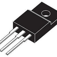
SIHF22N60S-E3 Vishay, SIHF22N60S-E3 Datasheet - Page 3

SIHF22N60S-E3
Manufacturer Part Number
SIHF22N60S-E3
Description
MOSFET Power 600V N-Channel Super junction TO-220FP
Manufacturer
Vishay
Datasheet
1.SIHF22N60S-E3.pdf
(7 pages)
Specifications of SIHF22N60S-E3
Transistor Polarity
N-Channel
Gate Charge Qg
75 nC
Resistance Drain-source Rds (on)
0.16 Ohms
Forward Transconductance Gfs (max / Min)
9.4 S
Drain-source Breakdown Voltage
600 V
Gate-source Breakdown Voltage
20 V
Continuous Drain Current
22 A
Power Dissipation
250 W
Mounting Style
Through Hole
Package / Case
TO-220 FP
Continuous Drain Current Id
22A
Drain Source Voltage Vds
600V
On Resistance Rds(on)
160mohm
Rds(on) Test Voltage Vgs
10V
Threshold Voltage Vgs Typ
4V
Power Dissipation Pd
250W
Operating Temperature Range
-55°C To +150°C
Transistor Case Style
TO-220FP
Rohs Compliant
Yes
Lead Free Status / RoHS Status
Lead free / RoHS Compliant
Lead Free Status / RoHS Status
Lead free / RoHS Compliant, Lead free / RoHS Compliant
TYPICAL CHARACTERISTICS (25 °C, unless otherwise noted)
Document Number: 91394
S10-1236-Rev. B, 24-May-10
Fig. 2 - Typical Output Characteristics, T
Fig. 1 - Typical Output Characteristics, T
50
40
30
20
10
30
24
18
12
0
6
0
0
0
V
V
4
4
DS
DS
4 .0 V
4 V
, Drain-to-Source Voltage (V)
, Drain-to-Source Voltage (V)
8
8
12
12
16
16
Bottom 4 V
Bottom 4 V
T
T
Top 15 V
J
J
Top 15 V
20
20
=
J
= 25
J
150 °C
= 150 °C
14 V
13 V
12 V
11 V
10 V
= 25 °C
14 V
13 V
12 V
11 V
10 V
V
9 V
8 V
7 V
6 V
5 V
V
9 V
8 V
7 V
6 V
5 V
GS
GS
°C
24
24
Fig. 4 - Normalized On-Resistance vs. Temperature
3.5
2.5
1.5
0.5
60
50
40
30
20
10
3
2
1
0
0
- 60 - 40 - 20 0
2
Fig. 3 - Typical Transfer Characteristics
I
V
D
GS
= 22 A
T
= 10 V
V
J ,
GS ,
Junction Temperature (°C)
T
4
J
= 150 °C
Gate-to-Source Voltage (V)
20 40 60 80 100 120 140 160 180
6
Vishay Siliconix
SiHF22N60S
T
J
8
= 25 °C
www.vishay.com
10
3


