SIHF22N60S-E3 Vishay, SIHF22N60S-E3 Datasheet - Page 4
SIHF22N60S-E3
Manufacturer Part Number
SIHF22N60S-E3
Description
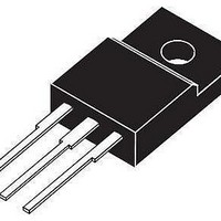
MOSFET Power 600V N-Channel Super junction TO-220FP
Manufacturer
Vishay
Datasheet
1.SIHF22N60S-E3.pdf
(7 pages)
Specifications of SIHF22N60S-E3
Transistor Polarity
N-Channel
Gate Charge Qg
75 nC
Resistance Drain-source Rds (on)
0.16 Ohms
Forward Transconductance Gfs (max / Min)
9.4 S
Drain-source Breakdown Voltage
600 V
Gate-source Breakdown Voltage
20 V
Continuous Drain Current
22 A
Power Dissipation
250 W
Mounting Style
Through Hole
Package / Case
TO-220 FP
Continuous Drain Current Id
22A
Drain Source Voltage Vds
600V
On Resistance Rds(on)
160mohm
Rds(on) Test Voltage Vgs
10V
Threshold Voltage Vgs Typ
4V
Power Dissipation Pd
250W
Operating Temperature Range
-55°C To +150°C
Transistor Case Style
TO-220FP
Rohs Compliant
Yes
Lead Free Status / RoHS Status
Lead free / RoHS Compliant
Lead Free Status / RoHS Status
Lead free / RoHS Compliant, Lead free / RoHS Compliant


SiHF22N60S
Vishay Siliconix
www.vishay.com
4
Fig. 5 - Typical Capacitance vs. Drain-to-Source Voltage
Fig. 6 - Typical Gate Charge vs. Gate-to-Source Voltage
100 000
10 000
1000
12.0
10.0
100
8.0
6.0
4.0
2.0
0.0
10
1
0
I
C
D
C
10
rss
= 22 A
oss
V
V
DS ,
DS
20
= 120 V
Q
Drain-to-Source Voltage (V)
V
G
30
DS
, Total Gate Charge (nC)
= 300 V
V
40
C
DS
V
C
C
iss
GS
rss
oss
= 480 V
= 0 V, f = 1 MHz
10
50
= C
= C
= C
gs
ds
gd
60 70
+ C
+ C
gd
gd
• C
80
ds
shorted
90 100
C
iss
100
0.0001
0.001
1000
1000
0.01
Fig. 7 - Typical Source-Drain Diode Forward Voltage
100
100
0.1
0.1
10
10
1
1
0.2
1
T
T
Single Pulse
Operation in this area limited
Fig. 8 - Maximum Safe Operating Area
C
J
T
= 150 °C
= 25 °C
J
= 150 °C
0.4
V
V
SD
DS
by R
10
, Source-to-Drain Voltage (V)
, Drain-to-Source Voltage (V)
DS(on)
0.6
100
0.8
T
J
S10-1236-Rev. B, 24-May-10
= 25 °C
Document Number: 91394
1
1000
10 ms
1 ms
100 µs
V
GS
1.2
= 0 V
10 000
1.4
Related parts for SIHF22N60S-E3
Image
Part Number
Description
Manufacturer
Datasheet
Request
R

Part Number:
Description:
357-036-542-201 CARDEDGE 36POS DL .156 BLK LOPRO
Manufacturer:
Vishay
Datasheet:
Part Number:
Description:
357-036-542-201 CARDEDGE 36POS DL .156 BLK LOPRO
Manufacturer:
Vishay
Datasheet:
Part Number:
Description:
357-036-542-201 CARDEDGE 36POS DL .156 BLK LOPRO
Manufacturer:
Vishay
Datasheet:
Part Number:
Description:
357-036-542-201 CARDEDGE 36POS DL .156 BLK LOPRO
Manufacturer:
Vishay
Datasheet:
Part Number:
Description:
357-036-542-201 CARDEDGE 36POS DL .156 BLK LOPRO
Manufacturer:
Vishay
Datasheet:
Part Number:
Description:
357-036-542-201 CARDEDGE 36POS DL .156 BLK LOPRO
Manufacturer:
Vishay
Datasheet:
Part Number:
Description:
357-036-542-201 CARDEDGE 36POS DL .156 BLK LOPRO
Manufacturer:
Vishay
Datasheet:
Part Number:
Description:
357-036-542-201 CARDEDGE 36POS DL .156 BLK LOPRO
Manufacturer:
Vishay
Datasheet:
Part Number:
Description:
357-036-542-201 CARDEDGE 36POS DL .156 BLK LOPRO
Manufacturer:
Vishay
Datasheet:
Part Number:
Description:
357-036-542-201 CARDEDGE 36POS DL .156 BLK LOPRO
Manufacturer:
Vishay
Datasheet:
Part Number:
Description:
357-036-542-201 CARDEDGE 36POS DL .156 BLK LOPRO
Manufacturer:
Vishay
Datasheet:
Part Number:
Description:
357-036-542-201 CARDEDGE 36POS DL .156 BLK LOPRO
Manufacturer:
Vishay
Datasheet:
Part Number:
Description:
357-036-542-201 CARDEDGE 36POS DL .156 BLK LOPRO
Manufacturer:
Vishay
Datasheet:
Part Number:
Description:
357-036-542-201 CARDEDGE 36POS DL .156 BLK LOPRO
Manufacturer:
Vishay
Datasheet:
Part Number:
Description:
357-036-542-201 CARDEDGE 36POS DL .156 BLK LOPRO
Manufacturer:
Vishay
Datasheet: