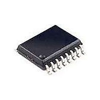
RE46C190S16F Microchip Technology, RE46C190S16F Datasheet - Page 22

RE46C190S16F
Manufacturer Part Number
RE46C190S16F
Description
MOSFET & Power Driver ICs 3V E-Cal Photo S.D. IC
Manufacturer
Microchip Technology
Type
CMOS Photoelectric Smoke Detector ASIC with Interconnect and Timer Moder
Datasheet
1.RE46C190S16F.pdf
(42 pages)
Specifications of RE46C190S16F
Product
Driver ICs - Various
Supply Voltage (max)
5 V
Supply Voltage (min)
2 V
Supply Current
1 uA
Maximum Operating Temperature
+ 60 C
Mounting Style
SMD/SMT
Minimum Operating Temperature
- 10 C
Output Current
- 4 mA
Output Voltage
8.5 V
Package / Case
SOIC-16
Input Voltage
5V
Ic Output Type
Open Drain
Sensor Case Style
SOIC
No. Of Pins
16
Supply Voltage Range
2V To 5V
Lead Free Status / RoHS Status
Lead free / RoHS Compliant
Available stocks
Company
Part Number
Manufacturer
Quantity
Price
Company:
Part Number:
RE46C190S16F
Manufacturer:
MCP
Quantity:
50
Company:
Part Number:
RE46C190S16F
Manufacturer:
MICROCHIP
Quantity:
12 000
RE46C190
4.3
A separate calibration mode is entered for each
measurement mode (Normal, Hysteresis, Hush and
Chamber Test) so that independent limits can be set for
each. In all calibration modes, the integrator output can
be accessed at the GLED output.
The Gamp output voltage, which represents the smoke
detection level, can be accessed at the RLED output.
The SmkComp output voltage is the result of the
comparison of Gamp with the integrator output, and
can be accessed at HB. The FEED input can be
clocked to step up the smoke detection level at RLED.
Once the desired smoke threshold is reached, the
TEST input is pulsed low to high to store the result.
The procedure is described in the following steps:
1.
2.
3.
4.
DS22271A-page 22
Power up with the bias conditions shown in
Figure
Drive TEST2 input from V
Programming mode. TEST2 should remain at
V
Apply a clock pulse to the TEST input to enter in
T1 mode. This initiates the calibration mode for
Normal Limits setting. The Integrator output saw
tooth should appear at GLED and the smoke
detection level at RLED. Clock FEED to
increase the smoke detection level as needed.
Once the desired smoke threshold is reached,
the IO input is pulsed low to high to enter the
result. See typical waveforms in
Operating the circuit in this manner, with nearly
continuous IRED current for an extended period
of time, may result in undesired or excessive
heating of the part. The duration of this step
should be minimized.
Apply a second clock pulse to the TEST input to
enter in T2 mode. This initiates the calibration
mode for Hysteresis Limits. Clock FEED as in
Step 3
is reached.Operating the circuit in this manner,
with nearly continuous IRED current for an
extended period of time, may result in undesired
or excessive heating of the part. The duration of
this step should be minimized.
DD
Smoke Calibration
through
4-1.
and apply pulse to IO, once desired level
Step 8
described below.
SS
to V
DD
to enter the
Figure
4-4.
5.
6.
7.
8.
Apply a clock pulse to the TEST input again to
enter in T3 mode and initiate calibration for Hush
Limits. Clock FEED as in the steps above and
apply a pulse to IO, once the desired level is
reached. Operating the circuit in this manner,
with nearly continuous IRED current for an
extended period of time, may result in undesired
or excessive heating of the part. The duration of
this step should be minimized.
Apply a clock pulse to the TEST input a fourth
time to enter in T4 mode, and initiate the
calibration for Chamber Test Limits. Clock FEED
and apply pulse to IO, once desired level is
reached. Operating the circuit in this manner,
with nearly continuous IRED current for an
extended period of time, may result in undesired
or excessive heating of the part. The duration of
this step should be minimized.
If the Long Term Drift Adjustment is enabled,
after all limits have been set, the long term drift
(LTD) baseline measurement must be made. To
do this, a measurement must be made under
no-smoke conditions. To enable the baseline
measurement, pull TEST from V
again and return to V
clear, pulse FEED low to high to make the
baseline measurement.
After limits have been set and baseline LTD
measurement has been made, pulse IO to store
all results in memory. Before this step, no limits
are stored in memory.
2010 Microchip Technology Inc.
SS
. Once the chamber is
SS
to V
BST


