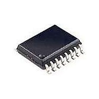
RE46C190S16F Microchip Technology, RE46C190S16F Datasheet - Page 24

RE46C190S16F
Manufacturer Part Number
RE46C190S16F
Description
MOSFET & Power Driver ICs 3V E-Cal Photo S.D. IC
Manufacturer
Microchip Technology
Type
CMOS Photoelectric Smoke Detector ASIC with Interconnect and Timer Moder
Datasheet
1.RE46C190S16F.pdf
(42 pages)
Specifications of RE46C190S16F
Product
Driver ICs - Various
Supply Voltage (max)
5 V
Supply Voltage (min)
2 V
Supply Current
1 uA
Maximum Operating Temperature
+ 60 C
Mounting Style
SMD/SMT
Minimum Operating Temperature
- 10 C
Output Current
- 4 mA
Output Voltage
8.5 V
Package / Case
SOIC-16
Input Voltage
5V
Ic Output Type
Open Drain
Sensor Case Style
SOIC
No. Of Pins
16
Supply Voltage Range
2V To 5V
Lead Free Status / RoHS Status
Lead free / RoHS Compliant
Available stocks
Company
Part Number
Manufacturer
Quantity
Price
Company:
Part Number:
RE46C190S16F
Manufacturer:
MCP
Quantity:
50
Company:
Part Number:
RE46C190S16F
Manufacturer:
MICROCHIP
Quantity:
12 000
RE46C190
4.4
As an alternative to the steps in
Calibration”
characterized, the limits and baseline can be entered
directly from a serial read/write calibration mode.
To enter this mode, follow these steps:
1.
2.
3.
4.
FIGURE 4-5:
DS22271A-page 24
5 bit
5 bit
5 bit
5 bit
TEST2
TEST
FEED
IO
Min Tsetup2 = 2 µs
Set up the application as shown in
Drive TEST2 input from V
Programming mode. TEST2 should remain at
V
Clock the TEST input to mode T6 (High = V
Low = V
read/write mode.
TEST now acts as a data input (High = V
Low = V
(High = V
LTD
options. The data sequence should be as
follows:
V
V
V
V
V
V
V
V
DD
DD
SS
BST
SS
BST
SS
DD
SS
Serial Read/Write
until all data has been entered.
baseline,
SS
,
SS
LTD sample (LSB first)
Chamber Test Limits (LSB first)
Hush Limits (LSB first)
Hysteresis Limits (LSB first),
BST
). FEED acts as the clock input
Min PW3 = 100 µs
, 6 clocks). This enables the serial
if
, Low = V
the
Timing Diagram for Mode T6.
functional
system
SS
Min T2 = 120 µs
). Clock in the limits,
SS
Section 4.3 “Smoke
to V
Min Tsetup1 = 1 µs
and
V
SS
has
DD
Figure
D1
parametric
to enter in
been
D2
4-1.
D3
BST
Min Thold1 = 1 µs
DD
well
,
,
D4
D5
D6
D7
Min PW1 = 10 µs
Then, the data sequence follows the pattern described
in
A serial data output is available at HB.
5.
5 bit
2 bit
2 bit
2 bit
3 bit
1 bit
1 bit
1 bit
1 bit
1 bit
Register
D8
After all 39 bits have been entered, pulse IO to
store into the EEPROM memory.
D9
D10
4-1:
Min T1 = 20 µs
Normal Limits (LSB first)
Photo Amp Gain Factor
Integration Time
IRED current
Low Battery Trip Point
Long Term Drift Enable
Hush Option
Low Battery Hush Enable
EOL enable
Tone Select
D11
D12
D13
2010 Microchip Technology Inc.
D14
D15
…
…
D39
Min PW2 = 10 ms
…


