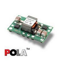
PMF8118TP Ericsson Power Modules, PMF8118TP Datasheet - Page 41

PMF8118TP
Manufacturer Part Number
PMF8118TP
Description
DC/DC Converters & Regulators 0.8-1.8V 10A Non-Iso Input 12V 18W
Manufacturer
Ericsson Power Modules
Series
PMFr
Datasheet
1.PMF8118TSR.pdf
(47 pages)
Specifications of PMF8118TP
Output Power
18 W
Input Voltage Range
10.8 V to 13.2 V
Number Of Outputs
1
Output Voltage (channel 1)
0.8 V to 1.8 V
Output Current (channel 1)
10 A
Package / Case Size
DIP
Output Type
POLA Non-Isolated Regulator
Product
Non-Isolated / POL
Lead Free Status / RoHS Status
Lead free / RoHS Compliant
Available stocks
Company
Part Number
Manufacturer
Quantity
Price
Company:
Part Number:
PMF8118TP
Manufacturer:
VICOR
Quantity:
12 000
Part Number:
PMF8118TP
Manufacturer:
ERICSSON/爱立信
Quantity:
20 000
Thermal Consideration continued
Definition of reference temperature (T
The reference temperature is used to monitor the temperature
limits of the product. Temperatures above maximum T
not allowed and may cause degradation or permanent
damage to the product. T
temperature range for normal operating conditions.
T
margins, proper operation and high reliability of the module.
Ambient Temperature Calculation
TBD
Prepared (also subject responsible if other)
SEC/D KEVIN YAN
Approved
SEC/D (Wei Zhang A)
PMF 8000 series
PMF 8000 series
PMF 8000 series
POL regulator, Input 10.8-13.2 V, Output 10 A/55 W
POL regulator, Input 10.8-13.2 V, Output 10 A/55 W
POL regulator, Input 10.8-13.2 V, Output 10 A/55 W
ref
is defined by the design and used to guarantee safety
ref
is also used to define the
ref
)
Checked
ref
are
Connections
PRODUCT SPEC.
No.
3/1301-BMR 643 8 Uen
Date
2006-02-08
Pin
1
2
3
4
5
6
7
8
9
10
Designation
Margin Down
Margin Up
V
V
Technical Specifi cation
Technical Specifi cation
Technical Specifi cation
EN/LZT 146 318 R1B February 2006
EN/LZT 146 318 R1B April 2006
EN/LZT 146 318 R1C Sep 2006
© Ericsson Power Modules AB
© Ericsson Power Modules AB
© Ericsson Power Modules AB
Rev
A
o
o
Inhibit
Track
GND
GND
Adjust
Sense
V
V
out
in
TOP VIEW
Reference
Function
Common ground connection
for the V
connections.
The positive input voltage
power node to the module.
Applying a low-level ground
signal to this input disables
the module’s output.
A 0.1 W 1% resistor must be
directly connected between
this pin and pin 7(GND) to set
the output voltage.
The sense input allows the
regulation circuit to
compensate for voltage drop
between the module and the
load.
The regulated positive power
output with respect to the
GND node.
Common ground connection
for the V
connections.
This is an analog control
input that enables the output
voltage to follow an external
voltage.
When this input is asserted to
GND, the output voltage is
decreased by 5% from the
nominal.
When this input is asserted to
GND, the output voltage is
increased by 5%.
in
in
and V
and V
out
out
power
power
4 (5)
41


