H5CX-AD-N AC24/DC12-24 Omron, H5CX-AD-N AC24/DC12-24 Datasheet - Page 42
H5CX-AD-N AC24/DC12-24
Manufacturer Part Number
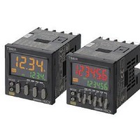
H5CX-AD-N AC24/DC12-24
Description
Stopwatches / Timers SCREW TERM RLY OUT Multi-Function
Manufacturer
Omron
Series
H5CXr
Datasheet
1.Y92P-CXT4B.pdf
(44 pages)
Specifications of H5CX-AD-N AC24/DC12-24
Timing Range
0.001 s to 9999 Hrs
Supply Voltage
12 V to 24 V
Current Rating (max)
100 mA
Display Type
4 Digit LCD Backlight
Product
Digital Timer
Termination Style
Screw
Time Range
0.001s-9999hrs
Power Consumption
2.4W
Reset Time
20ms
Character Size
11.5mm
Mounting Type
Panel
Time Range Min
0.001s
Supply Voltage Min
12V
Connector Type
Screw Terminal
Relay Type
Integrated
Function
Programmable (Multi-Function)
Circuit
SPDT (1 Form C)
Delay Time
0.001 Sec ~ 9999 Hrs
Output Type
Mechanical Relay
Contact Rating @ Voltage
5A @ 250VAC
Voltage - Supply
12 ~ 24VDC, 24VAC
Timing Adjustment Method
DIP Switches
Timing Initiate Method
Input Voltage, Trigger Signal
No. Of Digits / Alpha
4
Rohs Compliant
Yes
Lead Free Status / RoHS Status
Lead free / RoHS Compliant
For Use With
PNP/NPN
Lead Free Status / RoHS Status
Lead free / RoHS Compliant, Lead free / RoHS Compliant


42
H5CX-@-N
• H5CX models with a 24-VDC/12 to 24-VDC power supply use a
• An inrush current of approx. 10 A will flow for a short time when the
• Maintain voltage fluctuations in the power supply within the
• When turning the power ON and OFF, input signal reception is
• To allow for the startup time of peripheral devices (sensors, etc.),
• Inrush current generated by turning ON or OFF the power supply
• Make sure that all settings are appropriate for the application.
• Do not leave the Timer for long periods at a high temperature with
• EEPROM is used as backup memory when the power is
• Dispose of the product according to local ordinances as they apply.
• Attach the front panel when using the Timer. The tabs in the middle
transformer-free power supply method in which the power supply
terminals are not isolated from the signal input terminals. If a non-
isolating DC power supply is used, unwanted current paths may
occasionally burn or destroy internal components depending on
the wiring. Always check the wiring sufficiently before use.
power supply is turned ON. If the capacity of the power supply is
not sufficient, the Timer may not start. Be sure to use a power
supply with sufficient capacity.
specified operating voltage range.
possible, unstable, or impossible as shown in the diagram below.
the Timer starts timing operation between 200 to 250 ms after
power is turned ON. For this reason, in operations where timing
starts from power ON, the time display will actually start from 249
ms. If the set value is 249 ms or less, the time until output turns ON
will be a fixed value between 200 and 250. The present value
display will start from 250 ms. (Normal operation is possible for set
values of 250 ms or more.) In applications where a set value of 249
ms or less is required, use start timing with signal input.
may deteriorate contacts on the power supply circuit. Turn ON or
OFF to a device with the rated current of more than 10 A.
Unexpected operation resulting in property damage or accidents
may occur if the settings are not appropriate.
output current in the ON state. Doing so may result in the
premature deterioration of internal components (e.g., electrolytic
capacitors).
interrupted. The write life of the EEPROM is 100,000 writes.
The EEPROM is written at the following times:
of each of four sides secure the front panel to the main body. To
remove the panel, widen the four tabs and pull the panel toward
you. To mount the panel, fit all four tabs correctly into the grooves
on the main body.
• When the power supply is turned OFF
• When switching from Timer/Twin Timer Selection Mode or
Function Setting Mode to Run Mode
Power
supply
Precautions for Correct Use
Input
Tabs
ON
OFF
Impossible
200ms
Unstable
0 to 50 ms
Possible
5ms
Grooves
0 to 500 ms
Unstable Impossible
• When conforming to EMC standards, refer to the information
• This is a class A product. In residential areas it may cause radio
• H5CX-A@-N/-L@-N:
• H5CX-B@-N:
• When double insulation or reinforced insulation is required, apply
• Connect the input and output terminals to devices that do not have
provided in this datasheet for cable selection and other conditions.
interference, in which case the user may be required to take
adequate measures to reduce interference.
Basic insulation is provided between the power supply and input
terminals. (No insulation is provided between the power supply and
input terminals for the H5CX-@D-N.)
Basic insulation is provided between power supply and output
terminals, and between input and output terminals.
No insulation is provided between the power supply and input
terminals.
Basic insulation is provided between the power supply and output
terminals.
double insulation or reinforced insulation as defined in IEC 60664
that is suitable for the maximum operating voltage with clearances
or solid insulation.
any exposed charged parts.
Conformance to EN/IEC Standards