LM25066APSQE/NOPB National Semiconductor, LM25066APSQE/NOPB Datasheet
LM25066APSQE/NOPB
Specifications of LM25066APSQE/NOPB


Related parts for LM25066APSQE/NOPB

LM25066APSQE/NOPB Summary of contents
Page 1
... A black box (Telemetry/Fault Snap- shot) function captures and stores telemetry data and device status in the event of a warning or a fault. Features ■ Input voltage range: 2.9V to 17V Typical Application Schematic © 2011 National Semiconductor Corporation LM25066A ■ C/SMBus interface and PMBus compliant command structure ■ ...
Page 2
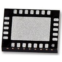
Connection Diagram Solder exposed pad to ground. Ordering Information Order Number LM25066APSQ LM25066APSQE LM25066APSQX www.national.com Top View LLP-24 Package Type Package Drawing LLP-24 SQA24B LLP-24 SQA24B LLP-24 SQA24B 2 30146002 Supplied As 1,000 units in tape and reel 250 units ...
Page 3
Pin Descriptions Pin Name Description No. Pad Exposed Exposed pad of LLP Pad package 1 ADR2 SMBUS address line 2 2 ADR1 SMBUS address line 1 3 ADR0 SMBUS address line 0 4 VDD Internal sub-regulator output 5 CL Current ...
Page 4
... Absolute Maximum Ratings If Military/Aerospace specified devices are required, please contact the National Semiconductor Sales Office/ Distributors for availability and specifications. VIN, SENSE to GND (Note 6) GATE, FB, UVLO/EN, OVLO, PGD, OUT to GND (Note 6) SCL, SDA, SMBA, CL, CB, ADR0, ADR1, ADR2, VDD, VAUX, DIODE, ...
Page 5
Symbol Parameter Gate Control (GATE Pin) I Source current GATE Fault Sink current POR Circuit Breaker sink current V Gate output voltage in normal operation GATE voltage with respect to ground GATE OUT Pin I OUT bias current, enabled OUT-EN ...
Page 6
Symbol Parameter Telemetry Accuracy IIN Current input full scale range FSR IIN Current input LSB LSB VAUX VAUX input full scale range FSR VAUX VAUX input LSB LSB VIN Input voltage full scale range FSR VIN Input voltage LSB LSB ...
Page 7
Typical Performance Characteristics T = 25° 12V. All graphs show junction temperature VIN Pin Current 6.0 5.5 5.0 4.5 4.0 3.5 3.0 -40 - 100 120 140 TEMPERATURE (°C) SENSE Pin ...
Page 8
GATE Pin Source Current VIN = 2. -40 - 100 120 140 TEMPERATURE (°C) PGD Low Voltage PGD Sink ...
Page 9
OVLO Threshold 1.167 VIN = 2.9V 1.166 VIN = 12V 1.165 1.164 1.163 VIN = 17V 1.162 -60 -40 - 100120140 TEMPERATURE (°C) FB Pin Hysteresis -23.0 -23.5 -24.0 -24.5 -25.0 -25.5 -26.0 -60 -40 ...
Page 10
Reference Voltage 2.75 2.74 2.73 2.72 2.71 2.70 -60 -40 - 100120140 TEMPERATURE (°C) Startup (short circuit V Startup (UVLO, OVLO) www.national.com 30146090 ) OUT 30146092 30146094 10 Startup (Insertion Delay) 30146091 Startup (5A Load) ...
Page 11
Current Limit Event (CL = GND) 30146096 Retry Event (Retry = GND) 30146098 IIN Measurement Accuracy (VIN - SENSE = 25 mV) 0.5 0.4 0.3 0.2 0.1 0.0 -0.1 -0.2 -0.3 -0.4 -0.5 - ...
Page 12
Block Diagram Functional Description The inline protection functionality of the LM25066A is de- signed to control the in-rush current to the load upon insertion of a circuit card into a live backplane or other “hot” power source, thereby limiting the ...
Page 13
Power Up Sequence The VIN operating range of the LM25066A is +2.9V to +17V with transient capability to +24V. Referring to Figure 2, as the voltage at VIN initially increases, the external N-channel MOSFET ( held off by ...
Page 14
Gate Control A charge pump provides the voltage at the GATE pin to en- hance the N-Channel MOSFET’s gate. During normal oper- ating conditions (t in Figure 2), the gate internal 22 µA current source. ...
Page 15
STATUS_INPUT (7Ch) register, the INPUT bit in the STATUS_WORD (79h) register, PFET_OP_FAULT bit in the DIAGNOSTIC_WORD (E1h) register will all be toggled high, and SMBA pin will be pulled low unless this feature is disabled using the ALERT_MASK (D8h) register. ...
Page 16
Under-Voltage Lockout (UVLO) The series pass MOSFET ( enabled when the input 1 supply voltage ( within the operating range defined by SYS the programmable under-voltage lockout (UVLO) and over- voltage lockout (OVLO) levels. Typically the ...
Page 17
FB to provide threshold hysteresis. The PGD output is forced low when ei- ther the UVLO/EN pin is below its threshold or ...
Page 18
Application Section DESIGN-IN PROCEDURE (Refer to Figure 6 for Typical Application Circuit) Shown here is the step-by-step procedure for hardware design of the LM25066A. This procedure refers to section numbers that provide detailed information on the following design steps. The ...
Page 19
The MOSFET manufacturer should be consulted for guidelines should be sufficiently low such that the power dissi- DS(on) pation at maximum load current ( LIM its junction temperature above the manufacturer’s recom- mendation. - ...
Page 20
The voltage across the sense resistor during power limit can be expressed as follows: where I is the current and For example, if the power ...
Page 21
TIMER CAPACITOR The TIMER pin capacitor (C ) sets the timing for the insertion T time delay, fault timeout period, and the restart timing of the LM25066A. A) Insertion Delay - Upon applying the system voltage (V ) ...
Page 22
FIGURE 10. UVLO and OVLO Thresholds Set By R1-R3 The procedure to calculate the resistor values is as follows: - Choose the upper UVLO threshold (V UVLO threshold (V ). UVL - Choose the upper OVLO threshold (V - The ...
Page 23
The four resistor values are calculated as follows: - Choose the upper and lower UVLO thresholds (V - Choose the upper and lower OVLO threshold ( OVL As an example, assume the application requires the following thresholds: V ...
Page 24
Option D: The OVLO function can be disabled by grounding the OVLO pin. The UVLO thresholds are set as described in Option B or Option C. POWER GOOD When the voltage at the FB pin increases above its threshold, the ...
Page 25
FIGURE 15. Adding Delay to the Power Good Output Pin SYSTEM CONSIDERATIONS A) Continued proper operation of the LM25066A hot swap circuit normally dictates that capacitance be present on the supply side of the connector into which the hot swap ...
Page 26
The high current path from the board’s input to the load (via Q ) and the return path should be parallel and close to each 1 other to minimize parasitic loop inductance. - The ground connections for the various ...
Page 27
PMBus ™ Command Support The device features an SMBus interface that allows the use of PMBus ™ commands to set warn levels, error masks, and Code Name 01h OPERATION 03h CLEAR_FAULTS 19h CAPABILITY 43h VOUT_UV_WARN_LIMIT 4Fh OT_FAULT_LIMIT 51h OT_WARN_LIMIT 57h ...
Page 28
Code Name D5h MFR_SPECIFIC_05 READ_PIN_PEAK D6h MFR_SPECIFIC_06 CLEAR_PIN_PEAK D7h MFR_SPECIFIC_07 GATE_MASK D8h MFR_SPECIFIC_08 ALERT_MASK D9h MFR_SPECIFIC_09 DEVICE_SETUP DAh MFR_SPECIFIC_10 BLOCK_READ DBh MFR_SPECIFIC_11 SAMPLES_FOR_AVG DCh MFR_SPECIFIC_12 READ_AVG_VIN DDh MFR_SPECIFIC_13 READ_AVG_VOUT DEh MFR_SPECIFIC_14 READ_AVG_IIN DFh MFR_SPECIFIC_15 READ_AVG_PIN E0h MFR_SPECIFIC_16 BLACK_BOX_READ E1h MFR_SPECIFIC_17 ...
Page 29
STANDARD PMBus™ COMMANDS OPERATION (01h) The OPERATION command is a standard PMBus ™ com- mand that controls the MOSFET switch. This command may be used to switch the MOSFET ON and OFF under host con- trol also used ...
Page 30
TABLE 7. VIN_OV_WARN_LIMIT Register Value Meaning 0h – 0FFEh VIN Over-voltage Warning detection threshold 0FFFh VIN Over-voltage Warning disabled VIN_UV_WARN_LIMIT (58h) The VIN_UV_WARN_LIMIT command is a standard PM- Bus ™ command that allows configuring or reading the thresh- old for ...
Page 31
STATUS_VOUT (7Ah) The STATUS_VOUT command is a standard PMBus ™ com- mand that returns the value of the VOUT UV Warn flag. Accesses to this command should use the PMBus ™ read Bit NAME 7 VOUT OV Fault 6 VOUT ...
Page 32
STATUS_CML (7Eh) The STATUS_CML is a standard PMBus ™ command that returns the value of a number of flags related to communica- Bit Memory Fault Detected Not supported, always 0 3 Processor Fault Detected Not supported, ...
Page 33
TABLE 20. MFR_MODEL Register Byte Name 0 Number of bytes 1 MFR ID-1 2 MFR ID-2 4Dh ‘M’ 3 MFR ID-3 4 MFR ID-4 5 MFR ID-5 6 MFR ID-6 7 MFR ID-7 8 MFR ID-8 MFR_REVISION (9Bh) Value The ...
Page 34
Manufacturer Specific PMBus™ Commands MFR_SPECIFIC_00: READ_VAUX (D0h) The READ_VAUX command will report the 12-bit ADC mea- sured auxiliary voltage. Voltages greater than or equal to 1.16V to ground will be reported at plus full scale (0FFFh). Voltages less than or ...
Page 35
TABLE 28. MFR_SPECIFIC_07 GATE MASK Definitions Bit NAME 7 Not used, always 0 6 Not used, always 0 5 VIN UV FAULT 4 VIN OV FAULT 3 IIN/PFET FAULT 2 OVERTEMP FAULT 1 Not used, always 0 0 CIRCUIT BREAKER ...
Page 36
MFR_SPECIFIC_10: BLOCK_READ (DAh) The BLOCK_READ command DIAGNOSTIC_WORD with input and output telemetry infor- mation (IIN, VOUT, VIN, PIN) as well as TEMPERATURE to capture all of the operating information of the LM25066A in a single SMBus transaction. The block is ...
Page 37
Telemetry and Warning Conversion Coefficients Table. TABLE 36. READ_AVG_IIN Register Value Meaning 0h – 0FFFh Average of measured values for current sense voltage MFR_SPECIFIC_15: READ_AVG_PIN The READ_AVG_PIN command will report the upper 12 bits of the average ...
Page 38
FIGURE 18. Command/Register and Alert Flow Diagram www.national.com 38 301460a2 ...
Page 39
Reading and Writing Telemetry Data and Warning Thresholds All measured telemetry data and user programmed warning thresholds are communicated in 12 bit two’s compliment bi- nary numbers read/written in 2 byte increments conforming to the Direct format as described in ...
Page 40
TABLE 42. Current and Power Telemetry and Warning Conversion Coefficients (R Commands *READ_IIN, READ_AVG_IIN MFR_IIN_OC_WARN_LIMIT *READ_IIN, READ_AVG_IIN MFR_IIN_OC_WARN_LIMIT *READ_PIN, READ_AVG_PIN, READ_PIN_PEAK MFR_PIN_OP_WARN_LIMIT *READ_PIN, READ_AVG_PIN, READ_PIN_PEAK MFR_PIN_OP_WARN_LIMIT Care must be taken to adjust the exponent coefficient, R, such that the value ...
Page 41
Reading Input and Output Voltage Coefficients for VIN and VOUT are fixed and are consistent between read telemetry measurements (e.g., READ_VIN, READ_AVG_VIN) and warning Step 1. Determine m' based on full scale analog input and full scale digital range: 2. ...
Page 42
Determining Telemetry Coefficients Empirically with Linear Fit The coefficients for telemetry measurements and warning thresholds presented in Table 41 are adequate for the ma- jority of applications. Current and power coefficients must be calculated per application as they are dependent ...
Page 43
PMBus™ Address Lines (ADR0, ADR1, ADR2) The three address lines are to be set high (connect to VDD), low (connect to GND), or open to select one of 27 addresses ADR2 ...
Page 44
SMBus Communications Timing Requirements Symbol F SMBus Operating Frequency SMB T Bus free time between Stop and Start Condition BUF T Hold time after (Repeated) Start Condition. After this HD:STA period, the first clock is generated. T Repeated Start Condition ...
Page 45
SMBA Response The SMBA effectively has two masks: 1. The Alert Mask Register at D8h, and 2. The ARA Automatic Mask. The ARA Automatic Mask is a mask that is set in response to a successful ARA read. An ARA ...
Page 46
Physical Dimensions www.national.com inches (millimeters) unless otherwise noted NS Package Number SQA24B 46 ...
Page 47
Notes 47 www.national.com ...
Page 48
... For more National Semiconductor product information and proven design tools, visit the following Web sites at: www.national.com Products Amplifiers www.national.com/amplifiers Audio www.national.com/audio Clock and Timing www.national.com/timing Data Converters www.national.com/adc Interface www.national.com/interface LVDS www.national.com/lvds Power Management www.national.com/power Switching Regulators www.national.com/switchers LDOs www.national.com/ldo LED Lighting www ...