EVL90WADP-LLCSR STMicroelectronics, EVL90WADP-LLCSR Datasheet - Page 30
EVL90WADP-LLCSR
Manufacturer Part Number
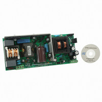
EVL90WADP-LLCSR
Description
EVAL BOARD PORTABLE PWR SUPPLY
Manufacturer
STMicroelectronics
Type
Power Factor Correctionr
Datasheets
1.L6563HTR.pdf
(49 pages)
2.L6599ADTR.pdf
(36 pages)
3.EVL90WADP-LLCSR.pdf
(29 pages)
4.EVL90WADP-LLCSR.pdf
(28 pages)
Specifications of EVL90WADP-LLCSR
Main Purpose
AC/DC, Primary and Secondary Side with PFC
Outputs And Type
1, Isolated
Power - Output
90W
Voltage - Output
19V
Current - Output
4.75A
Voltage - Input
90 ~ 264VAC
Regulator Topology
Boost
Frequency - Switching
130kHz
Board Type
Fully Populated
Utilized Ic / Part
L6563H, L6599A, SRK2000
Input Voltage
90 V to 264 V
Output Voltage
19 V
Dimensions
65 mm x 155 mm
Product
Power Management Modules
Supply Current
4.75 A
Lead Free Status / RoHS Status
Lead free / RoHS Compliant
For Use With/related Products
L6563H, L6599A, SRK2000
Other names
497-10377


Application information
7.7
30/36
the function is not used the pin has to be connected to a voltage greater than 1.24 V but
lower than 6V (worst-case value of the 7 V threshold).
Bootstrap section
The supply of the floating high-side section is obtained by means of a bootstrap circuitry.
This solution normally requires a high voltage fast recovery diode (D
charge the bootstrap capacitor C
replaces this external diode. It is realized by means of a high voltage DMOS, working in the
third quadrant and driven synchronously with the low side driver (LVG), with a diode in
series to the source, as shown in
Figure 31. Bootstrap supply: a) standard circuit;
The diode prevents any current can flow from the VBOOT pin back to Vcc in case that the
supply is quickly turned off when the internal capacitor of the pump is not fully discharged.
To drive the synchronous DMOS it is necessary a voltage higher than the supply voltage
Vcc. This voltage is obtained by means of an internal charge pump (
The bootstrap structure introduces a voltage drop while recharging CBOOT (i.e. when the
low side driver is on), which increases with the operating frequency and with the size of the
external power MOS. It is the sum of the drop across the R
across the series diode. At low frequency this drop is very small and can be neglected but,
as the operating frequency increases, it must be taken into account. In fact, the drop
reduces the amplitude of the driving signal and can significantly increase the R
external high-side MOSFET and then its conductive loss.
This concern applies to converters designed with a high resonance frequency (indicatively,
> 150 kHz), so that they run at high frequency also at full load. Otherwise, the converter will
run at high frequency at light load, where the current flowing in the MOSFETs of the half-
bridge leg is low, so that, generally, an R
check this point anyway and the following equation is useful to compute the drop on the
bootstrap driver:
b) internal bootstrap synchronous diode
Doc ID 15308 Rev 5
BOOT
Figure 31
. In the L6599A a patented integrated structure,
(DS)ON
b.
rise is not an issue. However, it is wise to
(DS)ON
and the forward drop
BOOT
Figure 31
,
Figure 31
b).
(DS)ON
L6599A
a) to
of the
Related parts for EVL90WADP-LLCSR
Image
Part Number
Description
Manufacturer
Datasheet
Request
R

Part Number:
Description:
STMicroelectronics [RIPPLE-CARRY BINARY COUNTER/DIVIDERS]
Manufacturer:
STMicroelectronics
Datasheet:
Part Number:
Description:
STMicroelectronics [LIQUID-CRYSTAL DISPLAY DRIVERS]
Manufacturer:
STMicroelectronics
Datasheet:

Part Number:
Description:
BOARD EVAL FOR MEMS SENSORS
Manufacturer:
STMicroelectronics
Datasheet:
Part Number:
Description:
NPN TRANSISTOR POWER MODULE
Manufacturer:
STMicroelectronics
Datasheet:
Part Number:
Description:
TURBOSWITCH ULTRA-FAST HIGH VOLTAGE DIODE
Manufacturer:
STMicroelectronics
Datasheet:
Part Number:
Description:
Manufacturer:
STMicroelectronics
Datasheet:
Part Number:
Description:
DIODE / SCR MODULE
Manufacturer:
STMicroelectronics
Datasheet:
Part Number:
Description:
DIODE / SCR MODULE
Manufacturer:
STMicroelectronics
Datasheet:
Part Number:
Description:
Search -----> STE16N100
Manufacturer:
STMicroelectronics
Datasheet:
Part Number:
Description:
Search ---> STE53NA50
Manufacturer:
STMicroelectronics
Datasheet:
Part Number:
Description:
NPN Transistor Power Module
Manufacturer:
STMicroelectronics
Datasheet:
Part Number:
Description:
DIODE / SCR MODULE
Manufacturer:
STMicroelectronics
Datasheet: