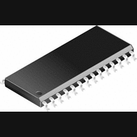
CS8415A-CS Cirrus Logic Inc, CS8415A-CS Datasheet - Page 10

CS8415A-CS
Manufacturer Part Number
CS8415A-CS
Description
IC, DIGITAL AUDIO RECEIVER, SOIC-28
Manufacturer
Cirrus Logic Inc
Specifications of CS8415A-CS
Audio Control Type
Digital
Control Interface
I2C, Serial
Control / Process Application
AV & DVD Receivers, CD-R, Digital Mixing Consoles
Supply Voltage Range
2.85V To 5.5V
Lead Free Status / RoHS Status
Contains lead / RoHS non-compliant
Available stocks
Company
Part Number
Manufacturer
Quantity
Price
Part Number:
CS8415A-CS
Manufacturer:
CIRRUS
Quantity:
20 000
Company:
Part Number:
CS8415A-CSR
Manufacturer:
CirrusLogic
Quantity:
569
Company:
Part Number:
CS8415A-CSZ
Manufacturer:
CIRRUS
Quantity:
108
Part Number:
CS8415A-CSZ
Manufacturer:
CRYSTAL
Quantity:
20 000
3. GENERAL DESCRIPTION
The CS8415A is a monolithic CMOS device which
receives and decodes audio data according to the
AES3, IEC60958, S/PDIF, and EIAJ CP1201 inter-
face standards.
Input data is either differential or single-ended. A
low jitter clock is recovered from the incoming data
using a PLL. The decoded audio data is output
through a configurable, 3-wire output port. The
channel status and user data are assembled in block
sized buffers and may be accessed through an SPI
or Two-Wire microcontroller port. For systems
with no microcontroller, a stand alone mode allows
direct access to channel status and user data output
pins.
Target applications include AVR, CD-R, DAT,
DVD, multimedia speakers, MD and VTR equip-
ment, mixing consoles, digital audio transmission
and receiving equipment, high quality D/A and
A/D converters, effects processors, set-top TV box-
es, and computer audio systems.
Figure 5 shows the supply and external connec-
tions to the CS8415A, when configured for opera-
tion with a microcontroller.
3.1
This data sheet assumes that the user is familiar
with the AES3 and S/PDIF data formats. It is advis-
able to have current copies of the AES3 and
IEC60958 specifications on hand for easy refer-
ence.
The latest AES3 standard is available from the Au-
dio Engineering Society or ANSI at www.aes.org
or www.ansi.org. Obtain the latest IEC60958 stan-
dard from ANSI or from the International Electro-
technical Commission at www.iec.ch. The latest
EIAJ CP-1201 standard is available from the Japa-
nese Electronics Bureau.
Crystal Application Note 22: Overview of Digital
Audio Interface Data Structures contains a useful
10
AES3 and S/PDIF Standards
Documents
tutorial on digital audio specifications, but it should
not be considered a substitute for the standards.
The paper An Understanding and Implementation
of the SCMS Serial Copy Management System for
Digital Audio Transmission, by Clifton Sanchez, is
an excellent tutorial on SCMS. It is available from
the AES as preprint 3518.
3.2
See Crystal Application Note 159: PLL Filter Op-
timization for the CS8415A, CS8420, and CS8427
by Patrick Muyshondt and Stuart Dudley Dimond
III for a tutorial on the CS8415A Phase-Locked-
Loop. This document gives equations for selecting
the proper PLL filter and guidelines on laying out
the PC board for the best performance.
4. SERIAL AUDIO OUTPUT PORT
A 3-wire serial audio output port is provided. The
port can be adjusted to suit the attached device set-
ting the control registers. The following parameters
are adjustable: master or slave, serial clock fre-
quency, audio data resolution, left or right justifica-
tion of the data relative to left/right clock, optional
one-bit cell delay of the first data bit, the polarity of
the bit clock and the polarity of the left/right clock.
By setting the appropriate control bits, many for-
mats are possible.
Figure 6 shows a selection of common output for-
mats, along with the control bit settings. A special
AES3 direct output format is included, which al-
lows the serial output port access to the V, U, and
C bits embedded in the serial audio data stream.
The P bit is replaced by a Z bit that marks the start
of each block. The received channel status block
start signal is only available in hardware mode, as
the RCBL pin.
In master mode, the left/right clock and the serial
bit clock are outputs, derived from the recovered
RMCK clock. In slave mode, the left/right clock
and the serial bit clock are inputs. The left/right
clock must be synchronous to the appropriate mas-
PLL Applications Note
CS8415A
DS470PP3


