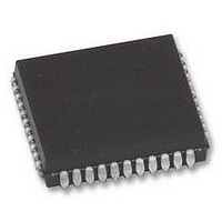
AT80C51RD2-SLSUM Atmel, AT80C51RD2-SLSUM Datasheet - Page 19

AT80C51RD2-SLSUM
Manufacturer Part Number
AT80C51RD2-SLSUM
Description
MCU, 8BIT, 8051, 5V, SPI, 20MHZ, 44PLCC
Manufacturer
Atmel
Specifications of AT80C51RD2-SLSUM
Controller Family/series
(8051) 8052
No. Of I/o's
32
Ram Memory Size
1280Byte
Cpu Speed
40MHz
No. Of Timers
3
No. Of Pwm Channels
5
Core Size
8bit
Oscillator Type
External Only
Processor Series
AT80x
Core
8051
Data Bus Width
8 bit
Program Memory Type
ROMLess
Data Ram Size
1280 B
Interface Type
UART, SPI
Maximum Clock Frequency
60 MHz
Number Of Programmable I/os
32
Number Of Timers
3
Operating Supply Voltage
2.7 V to 5.5 V
Maximum Operating Temperature
+ 85 C
Mounting Style
SMD/SMT
Package / Case
PLCC
3rd Party Development Tools
PK51, CA51, A51, ULINK2
Minimum Operating Temperature
- 40 C
Cpu Family
AT80
Device Core
8051
Device Core Size
8b
Frequency (max)
40MHz
Program Memory Size
Not Required
Total Internal Ram Size
1.25KB
# I/os (max)
32
Number Of Timers - General Purpose
3
Operating Supply Voltage (typ)
3.3/5V
Operating Supply Voltage (max)
5.5V
Operating Supply Voltage (min)
2.7V
Instruction Set Architecture
CISC
Operating Temp Range
-40C to 85C
Operating Temperature Classification
Industrial
Mounting
Surface Mount
Pin Count
44
Package Type
PLCC
Lead Free Status / RoHS Status
Lead free / RoHS Compliant
Lead Free Status / RoHS Status
Lead free / RoHS Compliant
Available stocks
Company
Part Number
Manufacturer
Quantity
Price
Company:
Part Number:
AT80C51RD2-SLSUM
Manufacturer:
Atmel
Quantity:
1 445
6.2
6.2.1
4188F–8051–01/08
Timer 2
Auto-reload Mode
The timer 2 in the
It is a 16-bit timer/counter: the count is maintained by two eight-bit timer registers, TH2 and TL2,
connected in cascade. It is controlled by T2CON register (See Table 6-2) and T2MOD register
(See Table 6-3). Timer 2 operation is similar to Timer 0 and Timer 1. C/T2 selects F
operation) or external pin T2 (counter operation) as the timer clock input. Setting TR2 allows TL2
to be incremented by the selected input.
Timer 2 has 3 operating modes: capture, autoreload and Baud Rate Generator. These modes
are selected by the combination of RCLK, TCLK and CP/RL2 (T2CON), as described in the
Atmel 8-bit Microcontroller Hardware description.
Refer to the Atmel 8-bit Microcontroller Hardware description for the description of Capture and
Baud Rate Generator Modes.
In
The auto-reload mode configures timer 2 as a 16-bit timer or event counter with automatic
reload. If DCEN bit in T2MOD is cleared, timer 2 behaves as in 80C52 (refer to the Atmel 8-bit
Microcontroller Hardware description). If DCEN bit is set, timer 2 acts as an Up/down
timer/counter as shown in Figure 6-2. In this mode the T2EX pin controls the direction of count.
When T2EX is high, timer 2 counts up. Timer overflow occurs at FFFFh which sets the TF2 flag
and generates an interrupt request. The overflow also causes the 16-bit value in RCAP2H and
RCAP2L registers to be loaded into the timer registers TH2 and TL2.
When T2EX is low, timer 2 counts down. Timer underflow occurs when the count in the timer
registers TH2 and TL2 equals the value stored in RCAP2H and RCAP2L registers. The under-
flow sets TF2 flag and reloads FFFFh into the timer registers.
The EXF2 bit toggles when timer 2 overflows or underflows according to the the direction of the
count. EXF2 does not generate any interrupt. This bit can be used to provide 17-bit resolution.
• Auto-reload mode with up or down counter
• Programmable clock-output
TS80C51RX2
TS80C51RX2
Timer 2 includes the following enhancements:
is compatible with the timer 2 in the 80C52.
AT/TS8xC51Rx2
OSC
/12 (timer
19


