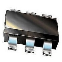
LTC3525ESC6-3#PBF Linear Technology, LTC3525ESC6-3#PBF Datasheet - Page 10

LTC3525ESC6-3#PBF
Manufacturer Part Number
LTC3525ESC6-3#PBF
Description
IC, SYNC STEP-UP DC/DC CONVERTER, SC70-6
Manufacturer
Linear Technology
Datasheet
1.LTC3525ESC6-3PBF.pdf
(14 pages)
Specifications of LTC3525ESC6-3#PBF
Primary Input Voltage
1.2V
No. Of Outputs
1
Output Voltage
3V
Output Current
400mA
No. Of Pins
6
Operating Temperature Range
-40°C To +85°C
Termination Type
SMD
Msl
MSL 1 - Unlimited
Rohs Compliant
Yes
Lead Free Status / RoHS Status
Lead free / RoHS Compliant
Available stocks
Company
Part Number
Manufacturer
Quantity
Price
LTC3525-3/
LTC3525-3.3/LTC3525-5
OPERATION
Component Selection
Inductor values between 4.7µH and 15µH are recom-
mended. In most applications 10µH will yield the best
compromise between size and efficiency. The inductor
should be a low loss ferrite design and must be rated for
peak currents of at least 400mA without saturating. Induc-
tors with lower DC resistance will improve efficiency. Note
that the inductor value does not have a significant effect
on ripple current, so while lower values will increase the
operating frequency, they do not reduce output voltage
ripple.
Some recommended inductor examples are Murata
LQH32C and Coilcraft LPO4812, LPO3310, DO3314,
DS1608 and MSS4020.
10
Table 1. Inductor Vendor Information
SUPPLIER
Murata
Coilcraft
Sumida
Table 2. Capacitor Vendor Information
SUPPLIER
Murata
Taiyo Yuden
TDK
AVX
SHDN
V
PHONE
USA: (814) 237-1431
(847) 639-6400
USA: (847) 956-0666
PHONE
USA: (814) 237-1431
(408) 573-4150
(847) 803-6100
(803) 448-9411
IN
Figure 3. Recommended Component Placement
FAX
USA: (814) 238-0490
(847) 639-1469
USA: (847) 956-0702
FAX
USA: (814) 238-0490
(408) 573-4159
(847) 803-6296
(803) 448-1943
SHDN
GND
V
IN
LTC3525
V
GND
A ceramic input bypass capacitor should be located as
close as possible to the V
minimum value of 1µF is recommended. If the battery is
more than a few inches away, a bulk tantalum decoupling
cap of at least 10µF is recommended on V
The output capacitor should also be a ceramic, located close
to the V
recommended. Increasing the value of the output capacitor
to 22µF will result in lower output ripple. Higher capacitor
values will only offer a small reduction in output ripple,
while reducing light load efficiency by causing the peak
inductor current to increase above its minimum value of
150mA. The input and output capacitors should be X5R
or X7R types, not Y5V.
OUT
SW
OUT
and GND pins. A minimum value of 10µF is
3525 F03
WEBSITE
www.murata.com
www.coilcraft.com
www.sumida.com
WEBSITE
www.murata.com
www.t-yuden.com
www.component.tdk.com
www.avxcorp.com
V
OUT
IN
and GND pins of the IC. A
IN
.
3525fb


